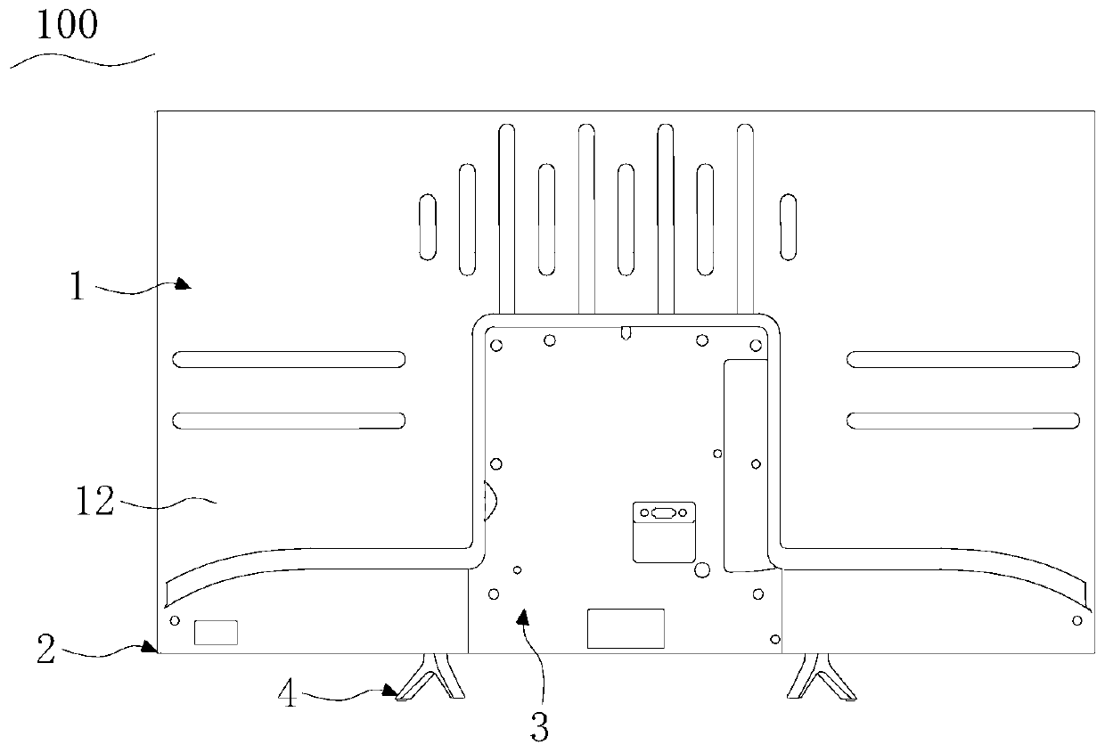
Display device
A technology of display equipment and rear shell, which is applied to the shell with display/control unit, electrical equipment shell/cabinet/drawer, instruments, etc., can solve the problem of high cost of the rear shell
- Summary
- Abstract
- Description
- Claims
- Application Information
AI Technical Summary
Problems solved by technology
Method used
Image
Examples
Embodiment 1
[0063] Embodiment 1, refer to Figure 5 to Figure 11 structure shown.
[0064] Figure 5 is a perspective view of the rear case of Embodiment 1 of the display device of the present invention.
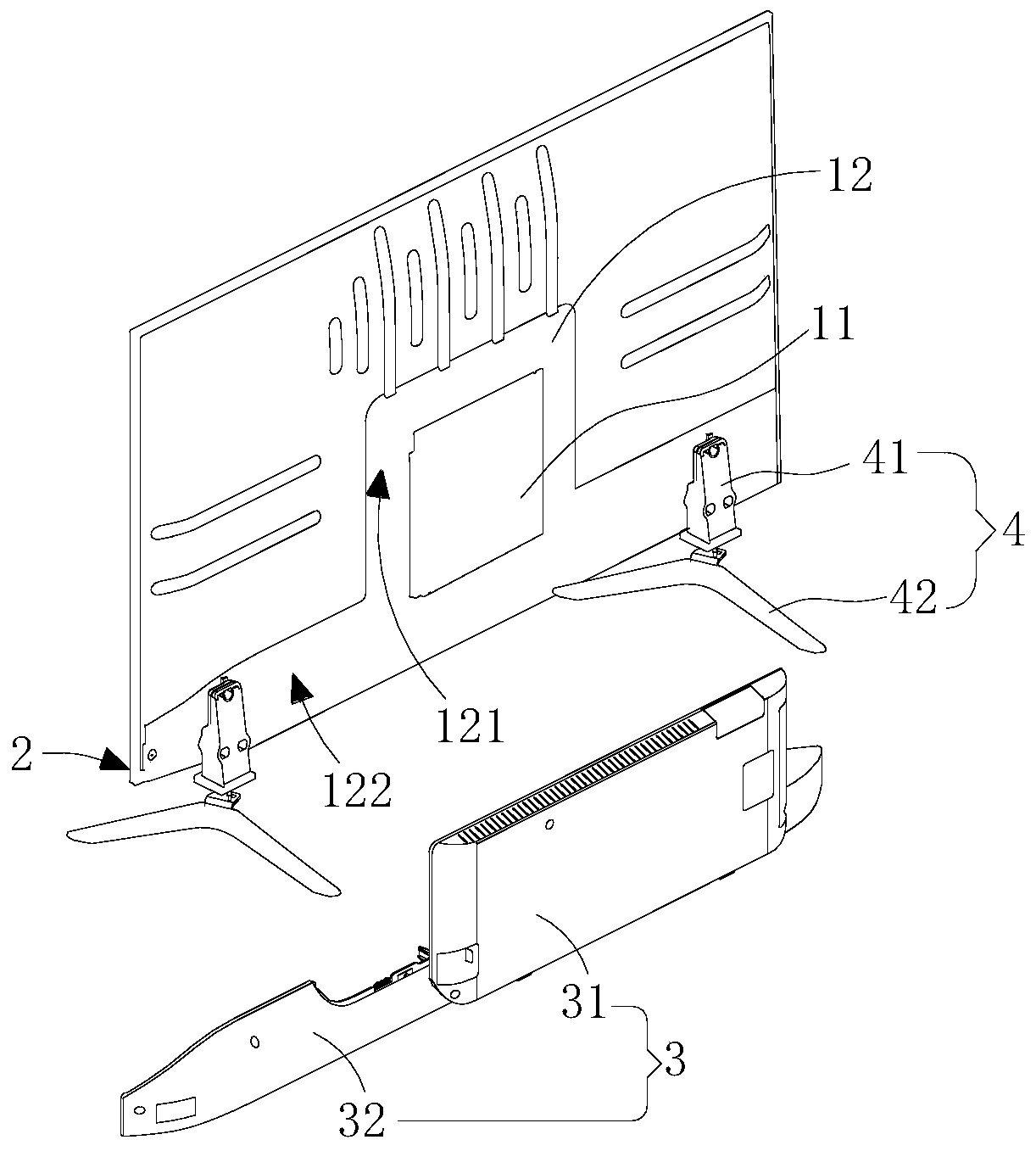
[0065] refer to Figure 5 As shown, the rear case 3 includes a rear case main segment 31 and at least one rear case extension segment 32, and the rear case main segment 31 and the rear case extension segment 32 can be detachably connected to the rear side surface of the back plate 12 , so that the rear case 3 realizes a split structure, the rear case main segment 31 and the rear case extension segment 32 can be combined freely, and achieve independence and modular disassembly.
[0066] The main section 31 of the rear case is mainly arranged relative to the main board 11 of the main body 1 of the display device, and the main board 11 is installed on the first installation area 121 of the back plate 12, so the main section 31 of the rear case covers the first installation area 121, A ...
Embodiment 2
[0079] Embodiment 2, refer to Figure 12 to Figure 15 structure shown.
[0080] The rear shell 3 of this embodiment is roughly the same as that of Embodiment 1, and the rear shell extension segment 32 and the rear shell main segment 31 are also arranged up and down. The difference is that the support plate 322 is provided with a slideway that opens backward. 3223, the slideway 3223 is in the shape of a semicircle. The main section 31 of the rear shell is provided with a slide rail 315 corresponding to the slideway 3223, and the slide rail 315 is adapted to the slideway 3223 and is located at the bottom of the main section 31 of the rear shell. The slide rail 315 can be slidably connected to the slideway 3223, so that the rear shell main section 31 is slidably engaged with the rear shell extension section 32 along the slideway 3223.
[0081] Wherein, the rear shell main section 31 is provided with an engaging plate 316 at its right side end, and the engaging plate 316 is in s...
Embodiment 3
[0083] Embodiment 3, refer to Figure 16 to Figure 19 structure shown.
[0084] Figure 16 It is an exploded view of the display device of Embodiment 3 among the display devices of the present invention.
[0085] refer to Figure 16 As shown, the rear case 3 of this embodiment is substantially the same as that of Embodiment 1, the difference is that there are two rear case extension segments 32, and the rear case main segment 31 and the rear case extension segment 32 are shown along the The device 100 is arranged in the length direction, and the two rear shell extension segments 32 are arranged on both sides of the rear shell main segment 31 . The rear case extension section 32 covers the second installation area 122 of the back panel 12 and forms a second receiving cavity with the back panel 12 , so that the sound component is located between the rear case extension section 32 and the back panel 12 . The rear shell extension section 32 is detachably fixedly connected to t...
PUM
 Abstract
Description
Claims
Application Information
 - R&D
- Intellectual Property
- Life Sciences
- Materials
- Tech Scout
- Unparalleled Data Quality
- Higher Quality Content
- 60% Fewer Hallucinations
Browse by: Latest US Patents, China's latest patents, Technical Efficacy Thesaurus, Application Domain, Technology Topic, Popular Technical Reports.
© 2025 PatSnap. All rights reserved.Legal|Privacy policy|Modern Slavery Act Transparency Statement|Sitemap|About US| Contact US: help@patsnap.com


