A battery protection circuit and a multi-level battery protection circuit

A protection circuit and voltage comparison circuit technology, applied in emergency protection circuit devices, electrical components, etc., can solve problems such as failure to realize battery protection, only charging or replacing batteries, and damage to low-voltage batteries

Active Publication Date: 2020-05-08
坎德拉(深圳)智能科技有限公司
View PDF11 Cites 0 Cited by
  • Summary
  • Abstract
  • Description
  • Claims
  • Application Information

AI Technical Summary

Problems solved by technology

The current product can only support one type of battery power supply, and it is impossible to work with batteries of different specifications at the same time
Once the battery of the product is low, you can only charge the battery or replace the battery; if a single product can use batteries of different specifications, on the one hand, the working time of the product can be extended, and the product will not stop working when the battery is low; on the other hand It can increase the versatility and convenience of the battery; however, the existing battery protection circuit is only for the overcharge, overdischarge, overvoltage, overcurrent, and overtemperature protection of the battery, and the application scenarios are battery charging and battery discharging; if A product uses multiple battery specifications at the same time. For example, a high-voltage battery and a low-voltage battery are connected to the load circuit for discharge. If the existing battery protection circuit is used, the high-voltage battery will discharge the low-voltage battery. Directly cause damage to the low-voltage battery, and cannot protect the respective batteries

Method used


Image

  • A battery protection circuit and a multi-level battery protection circuit
  • A battery protection circuit and a multi-level battery protection circuit
  • A battery protection circuit and a multi-level battery protection circuit

Examples


Embodiment Construction

[0025] It should be noted that, in the case of no conflict, the embodiments in the present application and the features in the embodiments can be combined with each other.

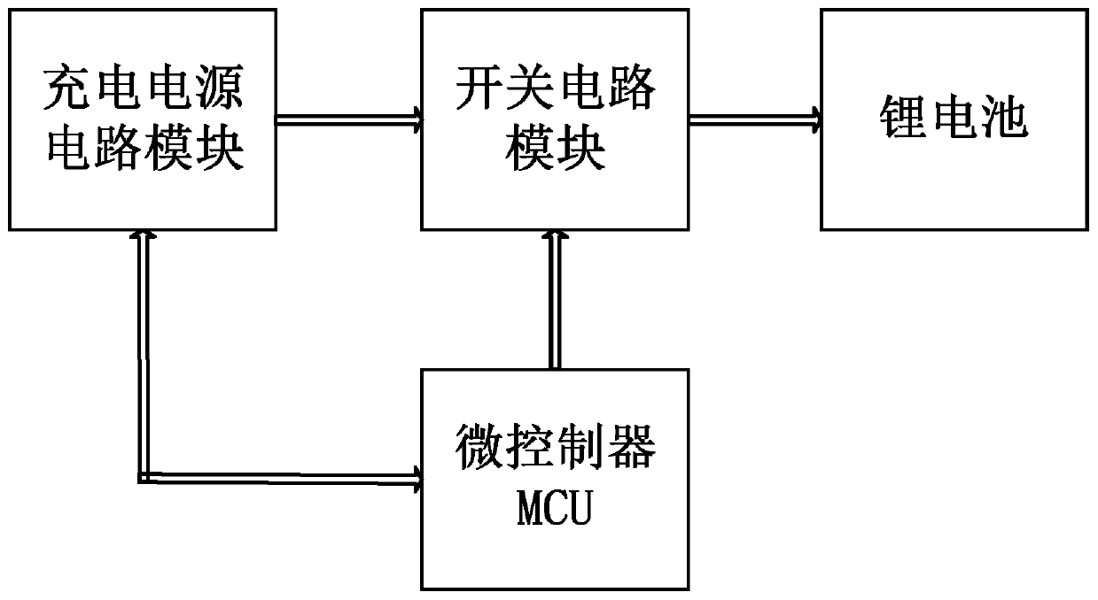
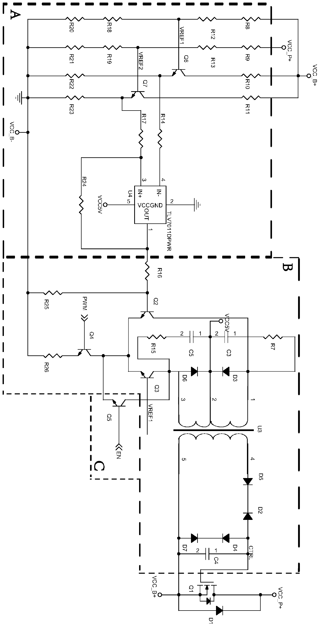
[0026] A battery protection circuit, refer to figure 2 , figure 2It is a circuit schematic diagram of a specific embodiment of a battery protection circuit in the present invention; the battery protection circuit includes a battery input terminal VCC_B+ connected to a battery, a circuit connection terminal VCC_P+ for voltage input and output, a voltage comparison circuit A, and a first switch control Circuit B, the first switching tube Q1 and the first diode D1, VCC_B+ is connected to the positive pole of the battery, VCC_B- is connected to the negative pole of the battery, the first switch control circuit B is used to control the on-off of the first switching tube Q1; the battery input terminals VCC_B+, The circuit connection terminal VCC_P+ is respectively connected to the input terminal of the voltag...


PUM


Abstract

The invention discloses a battery protection circuit, which comprises a battery input end connected with one battery, a circuit connection end for inputting and outputting voltage, a voltage comparison circuit, a first switch control circuit, a first switch tube and a first diode, wherein the first switch control circuit is used for controlling on / off of the first switch tube; and the voltage comparison circuit compares the voltage magnitude of the battery input end with the voltage magnitude of the circuit connection end to control output of the first switch control circuit, thereby controlling on / off of the first switch tube to ensure that the battery is not damaged by high voltage input from the circuit connection end. The invention further provides a multi-level battery protection circuit, which comprises at least two types of batteries and the battery protection circuits corresponding to the batteries one by one, wherein output ends of the batteries are connected with the batteryinput ends of the corresponding battery protection circuits; the circuit connection ends of the battery protection circuits are connected with an input end of a load circuit; and one battery corresponds to one battery protection circuit, thereby achieving independent protection on various batteries.

Description

technical field [0001] The invention relates to the field of battery protection, in particular to a battery protection circuit and a multi-level battery protection circuit. Background technique [0002] At present, the battery protection circuit is relatively mature and has been applied in a variety of products, such as electric vehicle battery chargers, mobile phone chargers, electric vehicle chargers, robot battery charging piles, etc.; the inside of the charger or the battery protection board of such products There is a battery protection circuit on it. In the prior art, charge and discharge protection chips or simulated charge and discharge protection circuits are usually used to protect the charging and discharging process of the battery to avoid battery failures, such as overvoltage, overcharge, and overdischarge of the battery. , Over-current, over-temperature protection, etc. [0003] Existing battery charge and discharge protection circuit includes battery, chargin...

Claims


Application Information

Patent Timeline
Patent Type & Authority Patents(China)
IPC IPC(8): H02H7/18
CPCH02H7/18
Inventor 王磊尹登庆赵冬亮刘稻
Owner 坎德拉(深圳)智能科技有限公司
Why Eureka
Try Eureka