Auxiliary anaesthetizing device for department of clinical anesthesia

An anesthesiology department and seat placement technology, which is applied in the field of auxiliary anesthesia devices and auxiliary anesthesia devices for clinical anesthesia departments, can solve problems such as inconvenience, patient discomfort, and difficulty in observation

Inactive Publication Date: 2019-11-19
李达
View PDF0 Cites 2 Cited by
  • Summary
  • Abstract
  • Description
  • Claims
  • Application Information

AI Technical Summary

Problems solved by technology

[0003] The purpose of the present invention is to solve the problem that when a doctor injects anesthetics to a patient at present, if the patient's veins are relatively slender and difficult to be observed, if the patient's blood vessel is pierced during the injection, the patient will easily feel uncomfortable. When the tape fixes the gauze at the wound, most of the tape is torn directly by hand, which requires two hands to operate at the same time, which is inconvenient. A clinical anesthesia auxiliary device is proposed.

Method used


Image

  • Auxiliary anaesthetizing device for department of clinical anesthesia
  • Auxiliary anaesthetizing device for department of clinical anesthesia
  • Auxiliary anaesthetizing device for department of clinical anesthesia

Examples


Embodiment Construction

[0020] The following will clearly and completely describe the technical solutions in the embodiments of the present invention with reference to the accompanying drawings in the embodiments of the present invention. Obviously, the described embodiments are only some, not all, embodiments of the present invention.

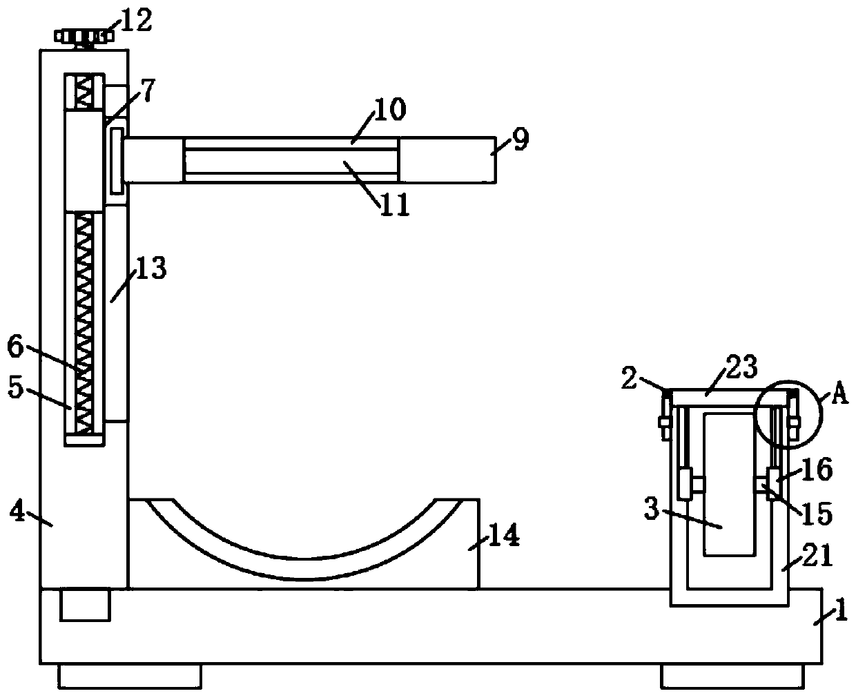
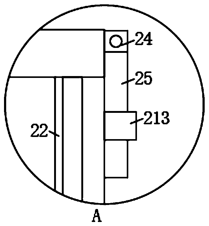
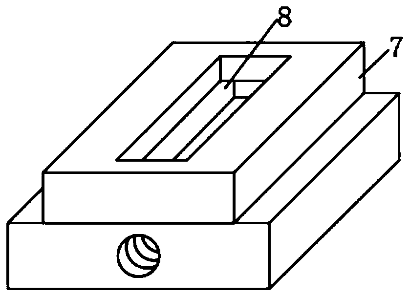
[0021] refer to Figure 1-5 , an auxiliary anesthesia device for clinical anesthesia, comprising a base 1, a storage mechanism 2 is fixedly connected to one side of the upper end of the base 1, an adhesive tape 3 is arranged inside the storage mechanism 2, and a vertical plate is clamped on the other side of the upper end of the base 1 4. There is a sliding chamber 5 inside the vertical plate 4, and a through groove 13 is provided on the inner wall of the sliding chamber 5 close to the middle of the base 1. The inner lower end of the sliding chamber 5 is connected with a screw 6 in rotation, and the upper end of the screw 6 passes through the sliding chamber The inne...


PUM


Abstract

The invention discloses an auxiliary anaesthetizing device for the department of clinical anesthesia. The auxiliary anaesthetizing device comprises a base, wherein a taking-in mechanism is fixedly connected to one side of the upper end of the base; an adhesive tape is arranged in the taking-in mechanism; a vertical plate is in clamping connection to the other side of the upper end of the base; a sliding cavity is formed in the vertical plate; a through groove is formed in the inner side wall adjacent to the middle part of the base, of the sliding cavity; a screw rod is rotatably connected to the lower end of the inner part of the sliding cavity; the upper end of the screw rod penetrates through the upper end of the inner part of the sliding cavity and extends to the upper end of the outerpart of the vertical plate; a rotating wheel is fixedly connected to one end outside the vertical plate, of the screw rod; and a sliding block is arranged on the outer side wall of the screw rod in asleeving manner. The auxiliary anaesthetizing device disclosed by the invention has the beneficial effects that a horizontal plate with the magnifying glass is arranged on the vertical plate, when theauxiliary anaesthetizing device is used, a limb of a patient can be placed on the placing seat, and the magnifying glass is moved to a position above an injection location to amplify the injection location, so that the situation that a doctor inserts a syringe needle to the blood vessel of the limb of the patient to enable the patient to have discomfort feeling can be avoided.

Description

technical field [0001] The invention relates to an auxiliary anesthesia device, in particular to an auxiliary anesthesia device for clinical anesthesia department, and belongs to the technical field of anesthesia auxiliary devices. Background technique [0002] When a doctor performs an operation on a patient's limb, he usually anesthetizes the patient first and then performs the operation. Currently, when a doctor injects an anesthetic into a patient, if the veins of the patient's limb are relatively slender and difficult to be observed, if they pierce the Inside the patient's blood vessels, it is easy to make the patient feel uncomfortable. When the staff uses tape to fix the gauze at the wound, most of them directly tear a piece of tape with their hands, which requires two hands to operate at the same time, which is relatively inconvenient. Contents of the invention [0003] The purpose of the present invention is to solve the problem that when a doctor injects anesthet...

Claims


Application Information

Patent Timeline
Patent Type & Authority Applications(China)
IPC IPC(8): A61M5/42A61F15/02
CPCA61F15/02A61M5/427
Inventor 李娜王立秀
Owner 李达
Why Eureka
Try Eureka