

Basketball sargent jump training device with high protection performance
A protective and basketball technology, which is applied in the field of basketball training, can solve the problems of athletes' injuries, boring, lacking, etc., and achieve the effect of improving the score of touching high, strong protection, and increasing fun
- Summary
- Abstract
- Description
- Claims
- Application Information
AI Technical Summary
Problems solved by technology
Method used
Image

Examples
Embodiment
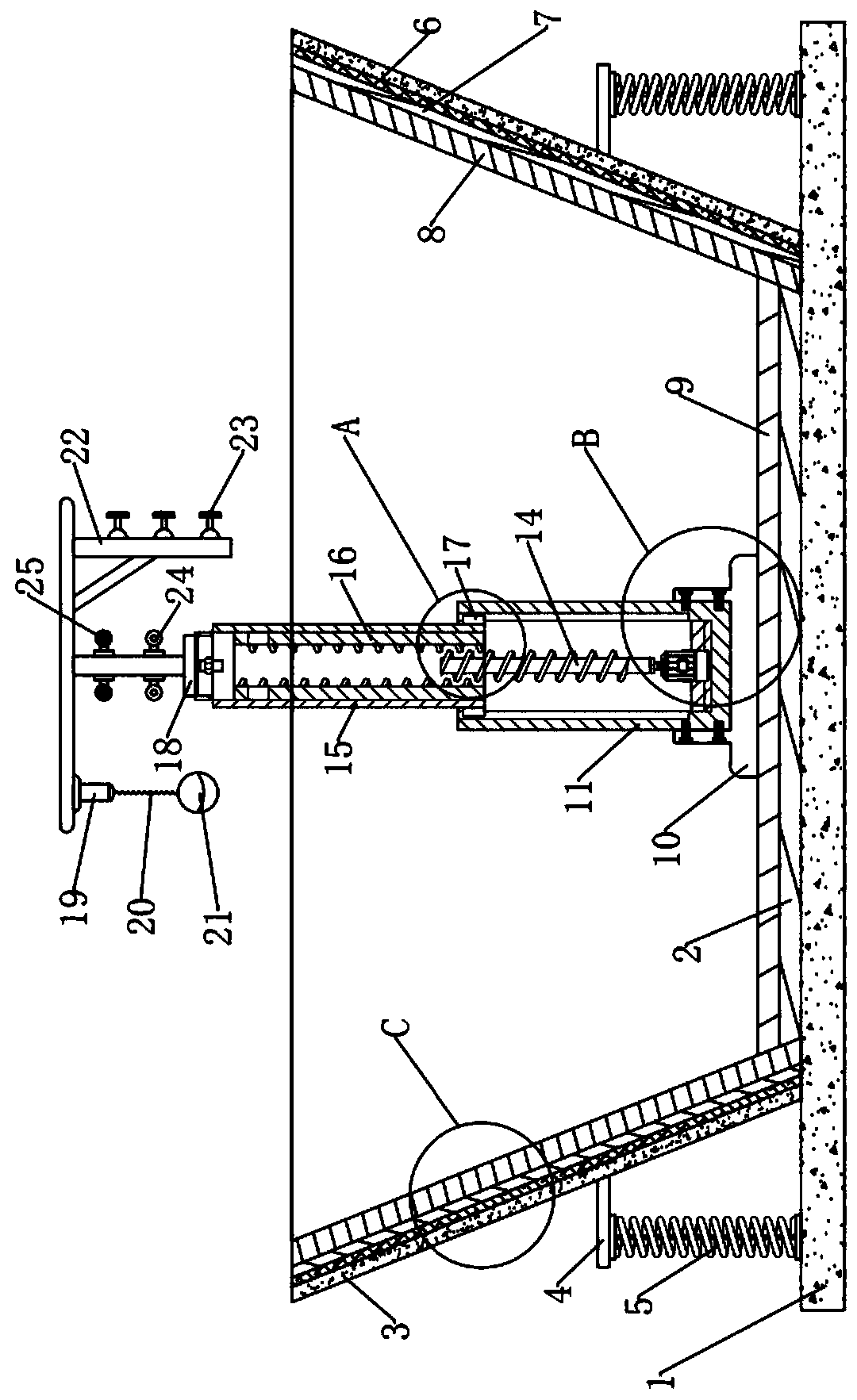
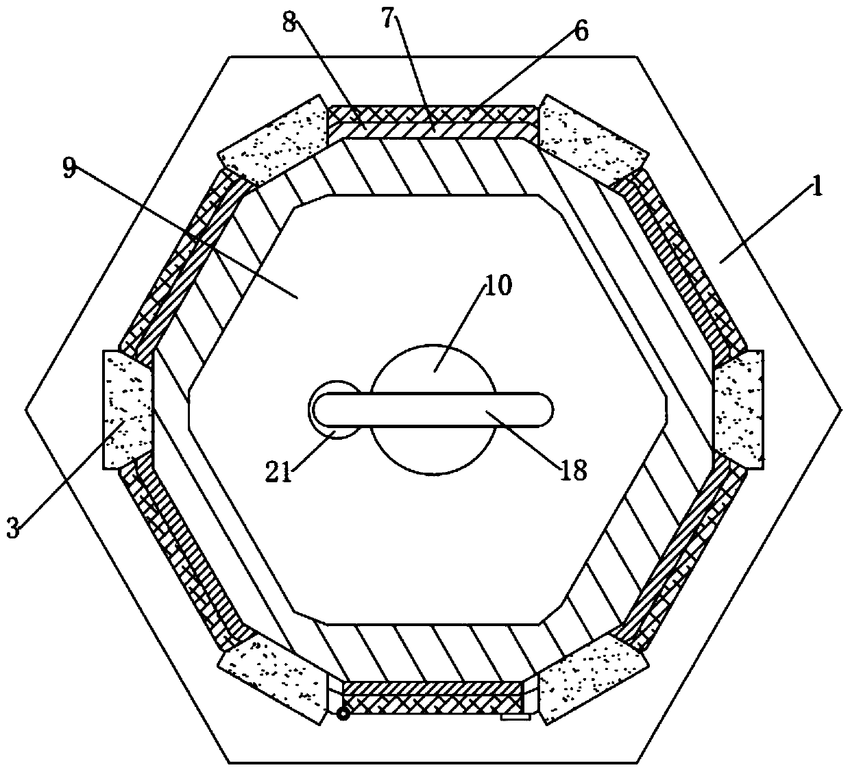
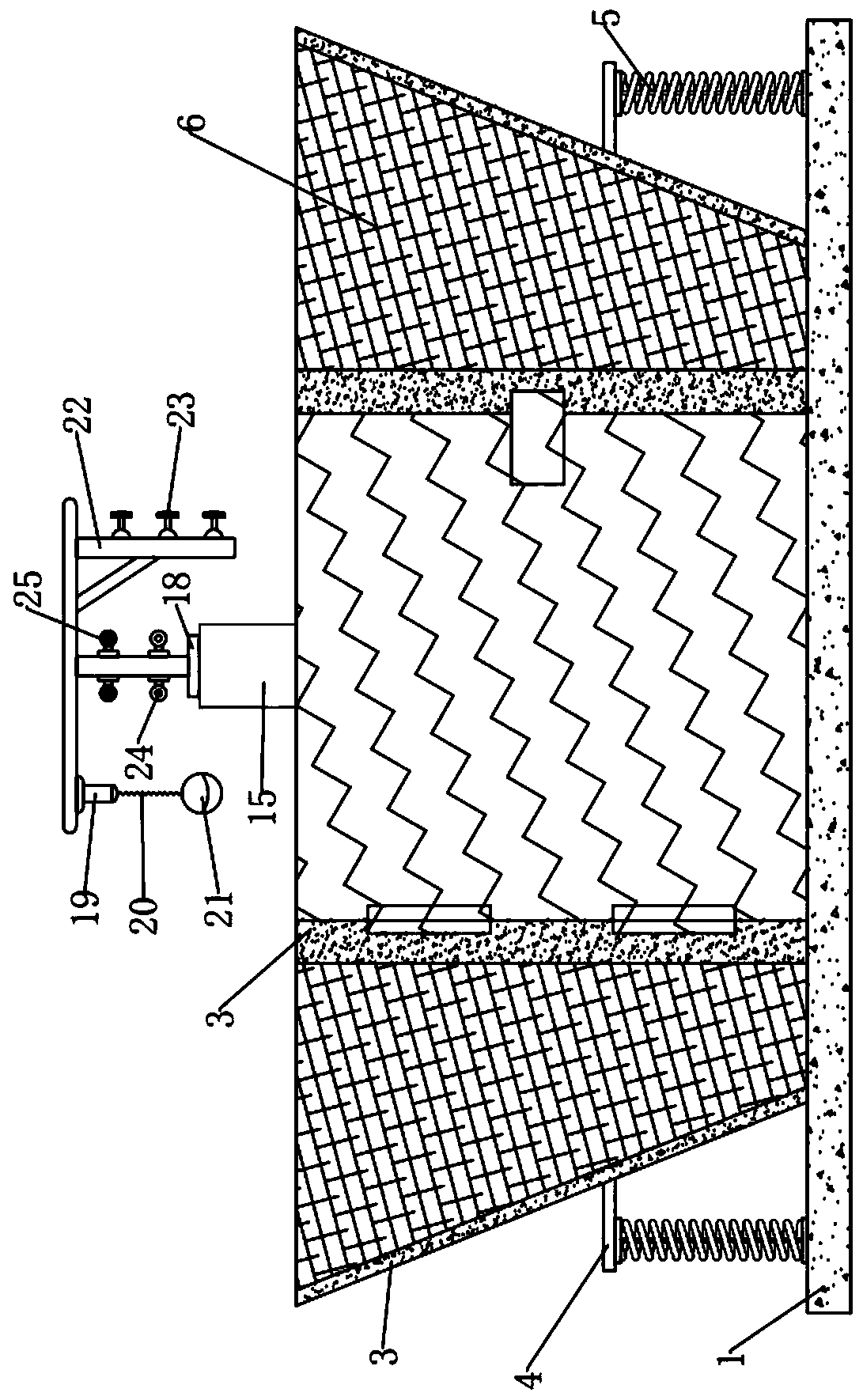
[0035] Example: Please refer to the attached Figure 1-6 , this case is a protective high-touch device for basketball training, including a mounting plate 1 and a shock-absorbing plate 2. The mounting plate 1 provides overall support for the device, and the shock-absorbing plate 2 reduces the impact on the body when the athlete touches the height and lands after taking off. Impact force, the shock absorbing plate 2 is installed on the upper wall of the mounting plate 1, the protective composition structure is installed on the mounting plate 1, the fixed support structure is connected to the shock absorbing plate 2, and the training adjustment structure is installed on the fixed structure;
[0036] In the specific implementation process, it should be pointed out that the protective structure in this case mainly includes: several pillars 3 with the same structure, several support plates 4 with the same structure, and protective components. The connection relationship and position...
PUM
 Abstract
Description
Claims
Application Information