
Intelligent power distribution cabinet

A power distribution cabinet, intelligent technology, applied in substation/power distribution device housing, substation/switchgear cooling/ventilation, etc., can solve the problems of short impact time, lack, easy occurrence, etc., and achieve strong protection ability and heat dissipation effect Good results

Active Publication Date: 2018-11-30
SHANDONG SHENGLI TONGHAI GRP DONGYING TIANLAN ENERGY SAVING SCI & TECH CO LTD
View PDF5 Cites 0 Cited by
  • Summary
  • Abstract
  • Description
  • Claims
  • Application Information

AI Technical Summary

Problems solved by technology

In addition, there is another characteristic of electrical equipment, that is, it is not suitable to be in an environment with a lot of moisture for a long time, especially to avoid excessive rainwater or excessively humid air continuously entering the power distribution cabinet, otherwise the life of the circuit and electrical equipment will be seriously affected. shortened, it is also easy to cause a short circuit
For conventional power distribution cabinets, once it encounters rainy days (very small and short-term rain is ignored, because the impact time is short and the impact is small), the external extremely humid air will continue to flow through the electrical equipment, which is extremely unfavorable
In addition, rainwater is easy to enter the power distribution cavity, which is more likely to cause problems.
However, the current power distribution cabinets are still lacking in the ability to take into account both heat dissipation and moisture resistance.

Method used


Image

  • Intelligent power distribution cabinet
  • Intelligent power distribution cabinet
  • Intelligent power distribution cabinet

Examples


Embodiment Construction

[0021] The present invention will be further described below in conjunction with the accompanying drawings and specific embodiments.

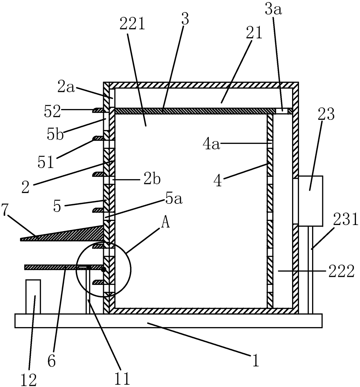
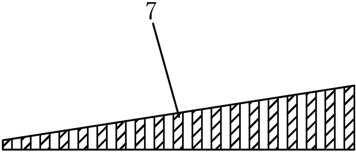
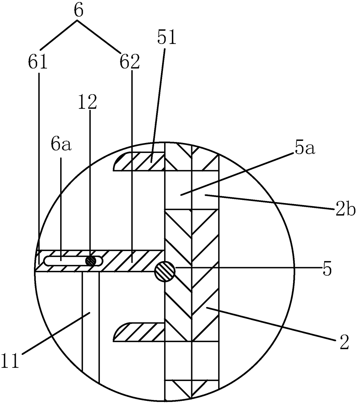
[0022] Such as Figure 1 to Figure 3 as shown in

[0023] An intelligent power distribution cabinet, including a base 1 fixed to the ground and a cabinet body 2 arranged on the base, the cabinet body is provided with a cabinet door,

[0024] Described cabinet body is provided with transverse clapboard 3, and transverse clapboard divides the interior of cabinet body into air inlet duct 21 and the lower main chamber below the air inlet duct, and the lower main chamber is provided with vertical clapboard 4, vertical clapboard The interior of the lower main cavity is divided into a power distribution cavity 221 and an exhaust cavity 222. An inner air hole 3a is provided on the diaphragm, one end of the inner air hole is connected to the air inlet, and the other end of the inner air hole is connected to the exhaust chamber. The indirect air inlet ...


PUM


Abstract

The invention discloses an intelligent power distribution cabinet. The intelligent power distribution cabinet comprises a base and a cabinet body, wherein the base is fixed with ground, the cabinet body is arranged on the base, a cabinet door is arranged on the cabinet body, a horizontal partition plate is arranged in the cabinet body, a vertical partition plate is arranged in a lower main cavity,an inner air hole is formed in the horizontal partition plate, an indirect air inlet and an air discharging pipe are arranged on the cabinet body, an air discharging and water prevention exhaust fanis arranged in the air discharging pipe, direct air inlets are formed in the cabinet body, direct air outlets are formed in the vertical partition plate, a vertical sealing plate is arranged outside the cabinet body, direct ventilation holes are formed in the vertical sealing plate, a rainwater driving plate is arranged on the vertical sealing plate, and an indirect ventilation hole is formed in the vertical sealing plate. The intelligent power distribution cabinet has the beneficial effects of cooling capability and also has dampproof and water inlet prevention capability in a rainy day, theadaptability switching can be automatically achieved according to an external environment, the intelligent power distribution cabinet is good in cooling effect and has high protection capability on internal electrical equipment.

Description

technical field [0001] The invention belongs to the technical field of intelligent equipment, and in particular relates to an intelligent power distribution cabinet. Background technique [0002] The power distribution cabinet is a common electrical assembly in life. The power distribution cabinet can assemble various electrical equipment and electrical components such as switchgear, measuring instruments, protective appliances and auxiliary equipment in a closed or semi-closed metal cabinet. The circuit can be turned on or off by means of a manual or automatic switch. Since various electrical equipment may be installed in the power distribution cabinet, it will continue to generate heat when it is working. In relatively high-temperature outdoor areas or environments, especially for distribution cabinets that are equipped with electrical equipment that is not suitable for long-term high-temperature environments As far as electric cabinets are concerned, heat dissipation is ...

Claims


Application Information

Patent Timeline
IPC IPC(8): H02B1/56H02B1/28
Inventor 冯艳
Owner SHANDONG SHENGLI TONGHAI GRP DONGYING TIANLAN ENERGY SAVING SCI & TECH CO LTD
Learn More