

Special lifting device for loading machine protection plate
A loader and guard plate technology, applied in the direction of load hanging components, transportation and packaging, can solve the problems of easy collision, damage to the frame guard plate, etc., and achieve the effect of strong protection, guaranteeing safety, and rapid use.
Inactive Publication Date: 2016-03-02
肖飚
View PDF7 Cites 0 Cited by
- Summary
- Abstract
- Description
- Claims
- Application Information
AI Technical Summary
Problems solved by technology
[0002] At present, the construction machinery manufacturing industry generally uses slings, hoisting ropes, wire rope slings, etc. for hoisting in the process of hoisting the lower frame guard plate of the loader, but it is easy to collide and slip during the hoisting process, causing damage to the loader lower frame guard plate.
Method used
View moreImage
Smart ImageViewing Examples

Examples
Embodiment Construction
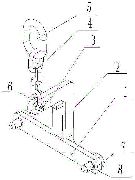
[0008] Such as figure 1 As shown, the present invention is a special spreader for a loader guard plate, comprising a balance beam 1, a boom 2, a chain sling 4 and a suspension ring 5, the suspension ring 5 is an O-shaped suspension ring, and the two ends of the balance beam 1 Positioning holes are provided, and positioning pins 7 and nuts 8 are provided on the positioning holes to fix the spreader and the lower frame guard plate of the loader; the bottom of the boom 2 is fixed on the balance beam 1, A balance point 3 is arranged on the upper part of the boom 2; the bottom of the chain rigging 4 is installed on the balance point 3 through a shackle 6, and the upper part is connected with the suspension ring 5.
Login to View More PUM
 Abstract
The invention discloses a special lifting device for a loading machine protection plate. The special lifting device comprises a balance beam (1), a lifting arm (2), chain rigging (4) and a lifting ring (5), wherein positioning holes are formed in the two ends of the balance beam (1); the bottom of the lifting arm (2) is fixed on the balance beam (1); a balance point (3) is arranged at the upper part of the lifting arm (2); the bottom of the chain rigging (4) is mounted on the balance point (3) through a shackle (6); the upper part of the chain rigging (4) is connected with the lifting ring (5). The special lifting device for the loading machine protection plate, provided by the invention, has the advantages of high protection performance, rapidness in use, high safety coefficient and the like.
Description
technical field [0001] The invention relates to a special spreader for the guard plate of a loader. Background technique [0002] At present, the engineering machinery manufacturing industry generally uses slings, hoisting ropes, wire rope slings, etc. for hoisting in the process of hoisting the lower frame guard of the loader, but it is easy to collide and slip during the hoisting process, causing damage to the lower frame guard of the loader. . Contents of the invention [0003] In order to solve the above problems, the present invention provides a special spreader for the loader guard plate, which has the advantages of strong protection, quick use, and high safety factor. [0004] The present invention adopts the following technical solutions: a special spreader for the loader guard plate, including a balance beam, a boom, a chain rigging and a suspension ring, positioning holes are provided at both ends of the balance beam, and the bottom of the boom is fixed On the ...
Claims
Login to View More Application Information
Patent Timeline
 IPC IPC(8): B66C1/22
CPCB66C1/22
Inventor肖飚
Owner肖飚