
Pilot valve

A pilot valve and valve technology, applied in the field of pilot valves, can solve the problems of inconvenience, complex structure, inconvenient adjustment of pipeline flow, etc., and achieve the effects of easy use, high efficiency and speed block.

Pending Publication Date: 2019-11-19
XINJIANG NORTH CONSTR GRP CO LTD
View PDF0 Cites 0 Cited by
  • Summary
  • Abstract
  • Description
  • Claims
  • Application Information

AI Technical Summary

Problems solved by technology

[0005] Aiming at the deficiencies of the prior art, the present invention provides a pilot valve, which solves the problems of complex structure, inconvenient use, and inconvenient adjustment of flow between pipelines during use

Method used


Image

  • Pilot valve
  • Pilot valve
  • Pilot valve

Examples


Embodiment Construction

[0026] The following will clearly and completely describe the technical solutions in the embodiments of the present invention with reference to the accompanying drawings in the embodiments of the present invention. Obviously, the described embodiments are only some, not all, embodiments of the present invention. Based on the embodiments of the present invention, all other embodiments obtained by persons of ordinary skill in the art without making creative efforts belong to the protection scope of the present invention.

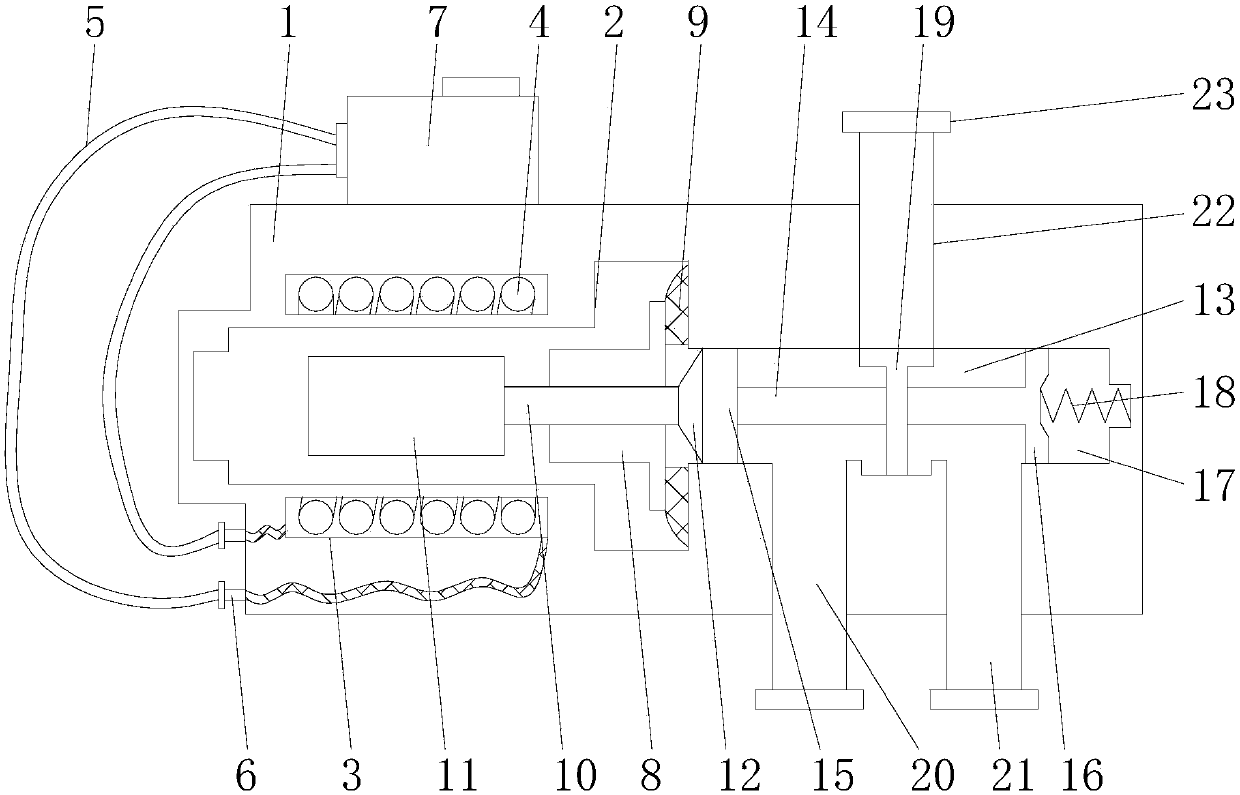
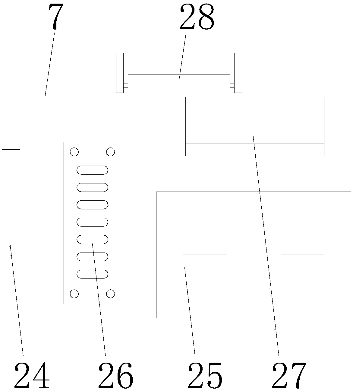
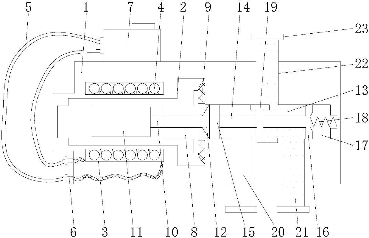
[0027] see Figure 1-4 As shown, an embodiment provided by the present invention: a pilot valve, including a valve body 1, a coil 4, a control box 7, a magnet 11, a push rod 10, a moving rod 14 and a movable plug 19, and the inside of the valve body 1 is provided with a set Cavity 2, a coil placement cavity 3 is arranged around the placement cavity 2, and the coil placement cavity 3 is arranged outside the placement cavity 2 in a ring shape, and the coils 4 in...


PUM


Abstract

The invention discloses a pilot valve, which comprises a valve main body, coils, a control box, a magnet, a pushing rod, a moving rod and a movable plug, wherein the valve main body is internally provided with a placing cavity, coil placing cavities are arranged around the placing cavity, the coils are installed in the coil placing cavities, the coils are electrically connected with the control box through a conductive wire, the right side in the placing cavity is provided with a fixing base, the fixing base is fixed in the placing cavity by a connecting block, the pushing rod is installed onthe fixing base, the left end of the pushing rod is provided with the magnet, the right end of the pushing rod is provided with the pushing block, a communicating cavity is arranged at the right sideof the placing cavity, the moving rod is installed in the communicating cavity, and a movable block is installed at the left end of the moving rod. Through arranging the valve main body, the coils, the control box, the magnet, the pushing rod, the moving rod and the movable plug, the problems of complex structure, inconvenient use, and inconvenient adjustment of flows between pipelines during theusing process are solved.

Description

technical field [0001] The invention relates to the technical field of valves, in particular to pilot valves. Background technique [0002] The pilot valve is used to control the supply to the restricted flow control of the pilot valve, also known as the main valve. For example, pilot operated valves may be placed in risers and branches of heating and cooling systems used in various domestic and industrial applications. Pilot valves are generally smaller valves compared to pilot operated valves and are advantageous to use because a small and easily accessible supply from the pilot valve can be used to control higher pressures or higher flow supply, which would otherwise require much greater force to operate. The pilot valve is conventionally positioned outside the body of the pilot valve and connected to the body by one or more fluid conduits having outlets into the main flow region of the pilot valve chamber. [0003] However, the existing pilot valve has the following d...

Claims


Application Information

Patent Timeline
Patent Type & Authority Applications(China)
IPC IPC(8): F16K31/06F16K11/065
CPCF16K31/0675F16K31/0603F16K11/065
Inventor 石体伟胡永彬王恩东倪志强李康杰
Owner XINJIANG NORTH CONSTR GRP CO LTD
Learn More