Article and manifold for thermal adjustment of a turbine component

a technology of turbine components and manifolds, which is applied in the direction of machines/engines, stators, lighting and heating apparatus, etc., can solve the problems of inability to optimize flow paths, inability to cool fluid post-impingement, and intense heat and external pressure on gas turbine airfoils such as nozzles

Active Publication Date: 2017-02-23
GENERAL ELECTRIC CO
View PDF4 Cites 11 Cited by
  • Summary
  • Abstract
  • Description
  • Claims
  • Application Information

AI Technical Summary

Benefits of technology

[0006]In another exemplary embodiment, a method for thermal adjustment of a turbine component includes providing a manifold having an impingement plate, the impingement plate defining a plenum and at least one impingement aperture. The at least one impingement aperture includes a flow modification structure. The method further includes dispersing a flow of a fluid from the plenum through the at least one impingement aperture, and altering the flow of the fluid by interaction with the flow modification structure. The flow of the fluid altered by the flow modification structure increases thermal contact between the fluid and a portion of the turbine component in comparison to an otherwise identical flow unimpeded by the flow modification structure.

Problems solved by technology

Gas turbines airfoils such as nozzles are subjected to intense heat and external pressures in the hot gas path.
However, crossflow in the post-impingement cavity and non-optimized flow paths inhibit fluid cooling in the post-impingement cavity.
The rigorous operating conditions, materials and manufacturing techniques have maintained or even exacerbated crossflow in the post-impingement cavity and non-optimized flow paths.

Method used


Image

  • Article and manifold for thermal adjustment of a turbine component
  • Article and manifold for thermal adjustment of a turbine component
  • Article and manifold for thermal adjustment of a turbine component

Examples


Embodiment Construction

[0020]Provided are exemplary articles, airfoil components and methods of forming articles and airfoil components. Embodiments of the present disclosure, in comparison to articles and methods not utilizing one or more features disclosed herein, better accommodate differential thermal expansion, increase tolerance of aerodynamic loads, improve cooling, improve durability, increase efficiency, improve local back flow margin and improve film effectiveness.

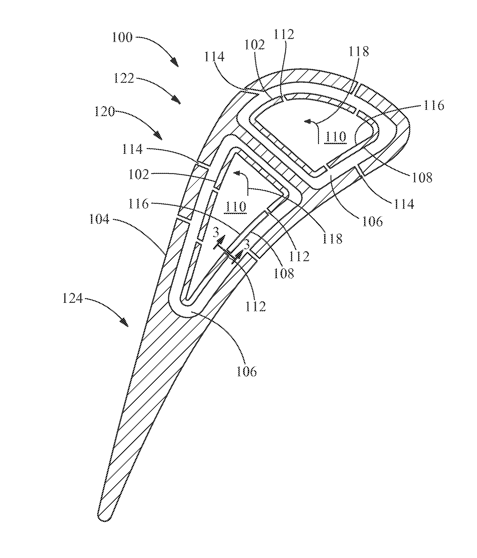
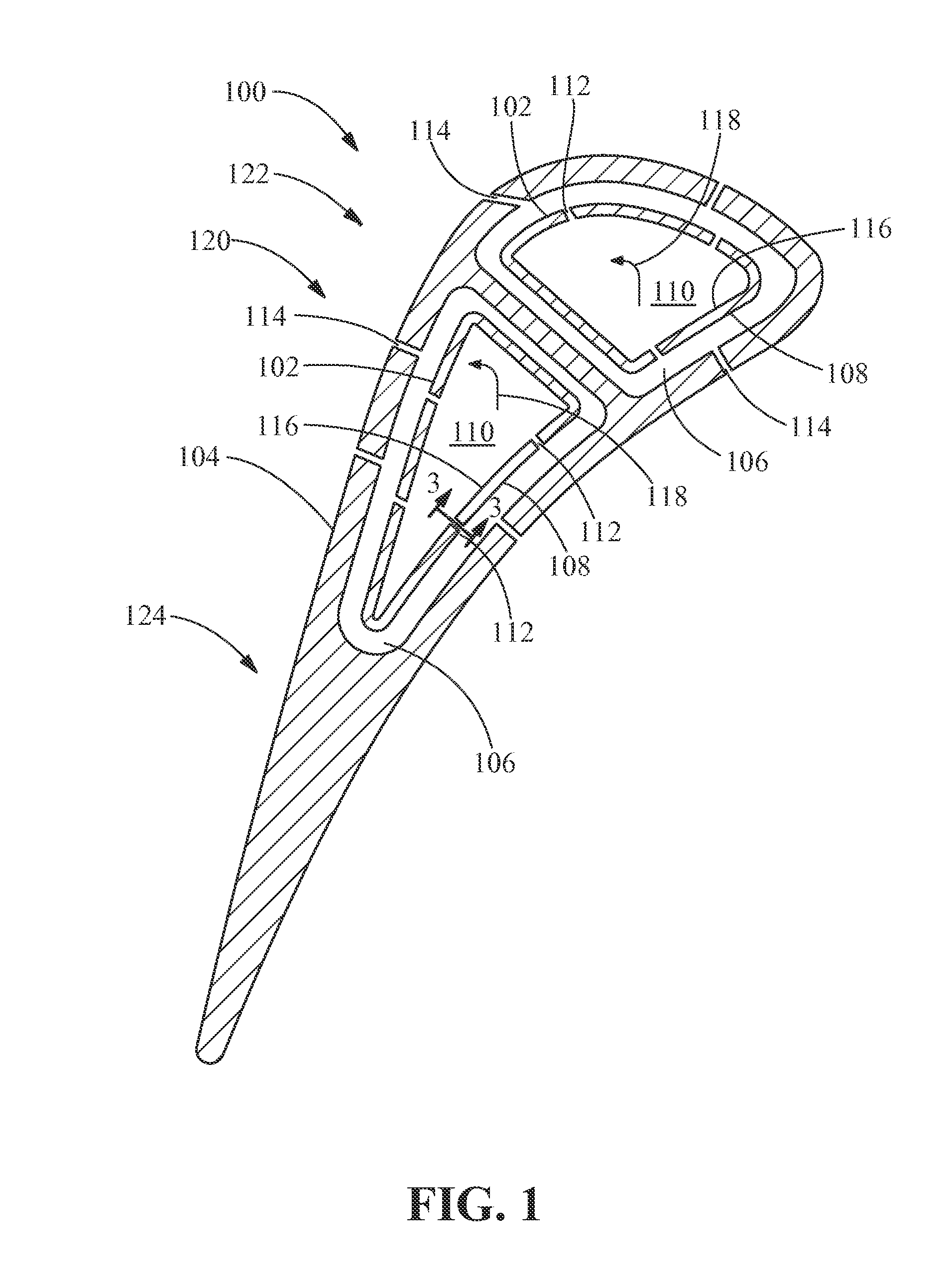
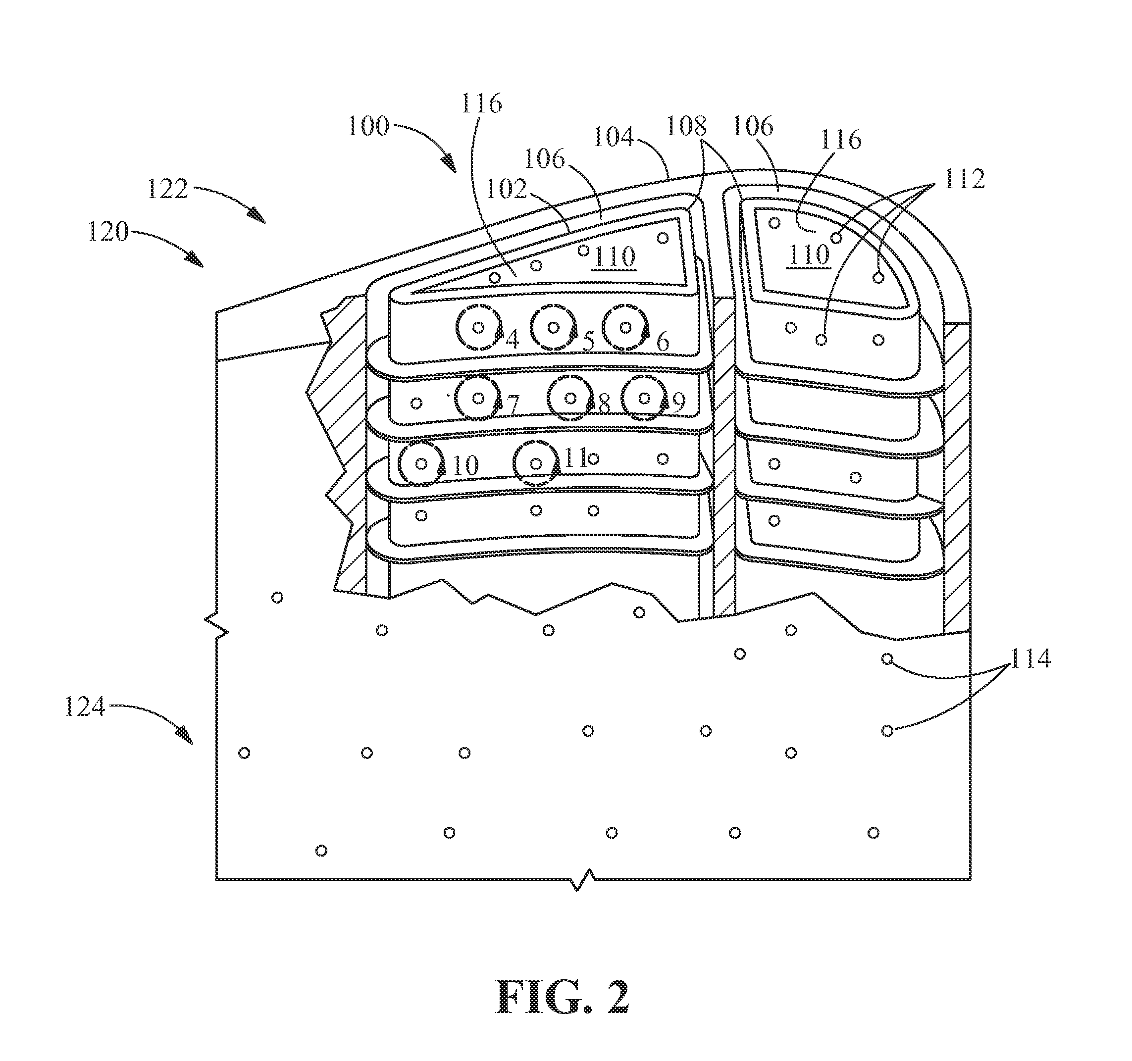
[0021]Referring to FIGS. 1 and 2, in one embodiment an article 100 includes a manifold 102, an article wall 104 and a post-impingement cavity 106 disposed between the manifold 102 and the article wall 104. The manifold 102 includes an impingement plate 108. The impingement plate 108 defines a plenum 110 and at least one impingement aperture 112. The article wall 104 includes at least one external aperture 114. The plenum 110 includes a plenum surface 116. The post-impingement cavity 106 is arranged to receive a fluid 118 from the plenu...


PUM


Abstract

An article is disclosed including a manifold, an article wall having at least one external aperture, and a post-impingement cavity disposed between the manifold and the article wall. The manifold includes an impingement plate defining a plenum having a plenum surface, and at least one impingement aperture. The at least one impingement aperture interfaces with the plenum at an intake aperture having a flow modification structure, which, together with the at least one impingement aperture, defines an exhaust aperture. The manifold exhausts a fluid from the plenum into the intake aperture, through the at least one impingement aperture, out the exhaust aperture, into the post-impingement cavity, and through the at least one external aperture.

Description

FIELD OF THE INVENTION[0001]The present invention is directed to articles and manifolds for thermal adjustment of turbine components. More particularly, the present invention is directed to articles and manifolds for thermal adjustment of turbine components including impingement flow modification structures.BACKGROUND OF THE INVENTION[0002]Gas turbines airfoils such as nozzles are subjected to intense heat and external pressures in the hot gas path. These rigorous operating conditions are exacerbated by advances in the technology, which may include both increased operating temperatures and greater hot gas path pressures. As a result, gas turbine nozzles are sometimes cooled by flowing a fluid through a manifold inserted into the core of the nozzle, which exits the manifold through impingement holes into a post-impingement cavity, and which then exits the post-impingement cavity through apertures in the exterior wall of the nozzle, forming a film layer of the fluid on the exterior of...

Claims


Application Information

Patent Timeline
Patent Type & Authority Applications(United States)
IPC IPC(8): F01D5/18
CPCF01D5/185F01D25/12F05D2220/30F01D5/189F05D2250/32F05D2250/324F05D2260/201F05D2260/2212F23R3/002F23R2900/03044F23R2900/03045F01D5/186F01D9/02F02C7/12F23R2900/03043
Inventor SEZER, IBRAHIMITZEL, GARY MICHAELMALDONADO, JAIME JAVIERDUTTA, SANDIP
Owner GENERAL ELECTRIC CO
Why Eureka
Try Eureka