
Heat insulation evaporator for micro-channel refrigeration system

A technology of adiabatic evaporation and refrigeration system, which is applied in the direction of evaporator/condenser, refrigerator, refrigeration components, etc., which can solve the problems of bulky size and the inability to install small electronic devices with high power to achieve small size, convenient heat dissipation operation, The effect of a simple structure

Active Publication Date: 2019-11-22
山东凌工新能源科技有限公司
View PDF8 Cites 0 Cited by
  • Summary
  • Abstract
  • Description
  • Claims
  • Application Information

AI Technical Summary

Problems solved by technology

[0002] With the development of the precision instrument industry, there are more and more high-density and high-power miniaturized electronic devices, and the heat dissipation of electronic devices has gradually become an urgent problem to be solved. Efficiency, but as a commonly used evaporator in refrigeration systems, it is limited by its bulk and cannot be installed in small electronic devices for high-power work. Therefore, a suitable evaporator structure is needed to apply to cooling for small electronic devices to dissipate heat in the system

Method used


Image

  • Heat insulation evaporator for micro-channel refrigeration system
  • Heat insulation evaporator for micro-channel refrigeration system

Examples


Embodiment Construction

[0021] The following will clearly and completely describe the technical solutions in the embodiments of the present invention with reference to the accompanying drawings in the embodiments of the present invention. Obviously, the described embodiments are only some, not all, embodiments of the present invention. Based on the embodiments of the present invention, all other embodiments obtained by persons of ordinary skill in the art without creative work, any modifications, equivalent replacements, improvements, etc., shall be included in the protection scope of the present invention Inside.

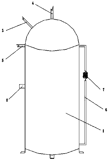
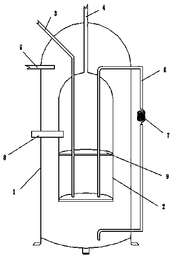
[0022] Such as figure 1 , figure 2 As shown, an adiabatic evaporator for a microchannel refrigeration system, the adiabatic evaporator includes an inner tank 2 for evaporation of liquid fluorine, an outer tank 1 for condensation of gaseous fluorine, and an outer tank 1 for transporting liquid fluorine The first pipeline 3, the second pipeline 4 for transporting gaseous fluorine for coo...


PUM


Abstract

The invention discloses a heat insulation evaporator for a micro-channel refrigeration system. The heat insulation evaporator comprises an inner tank body, an outer tank body, a first pipeline used for conveying liquid fluorine, a second pipeline used for conveying gaseous fluorine to carry out refrigeration and heat dissipation, a third pipeline used for conveying high-temperature gaseous fluorine and a fourth pipeline used for reflowing the liquid fluorine, wherein the outer tank body sleeves the inner tank body; one end of the first pipeline communicates with a liquid storage tank, and theother end of the first pipeline sequentially penetrates through the side walls of the outer tank body and the inner tank body and is arranged in the inner tank body; one end of the second pipeline communicates with the top end of the inner tank body, and the other end of the second pipeline sequentially penetrates through the top end of the outer tank body and a required heat dissipation region and is connected to an air inlet of a compressor, an air outlet of the compressor is connected to one end of the third pipeline, and the other end of the third pipeline communicates with the outer tankbody; and one end of the fourth pipeline is inserted into the outer tank body from the bottom end of the side wall of the outer tank body, and the other end of the fourth pipeline is inserted into theinner tank body, and the fourth pipeline is provided with a capillary throttling valve.

Description

technical field [0001] The invention relates to the field of electronic devices, in particular to an adiabatic evaporator used in a micro-channel refrigeration system. Background technique [0002] With the development of the precision instrument industry, there are more and more high-density and high-power miniaturized electronic devices, and the heat dissipation of electronic devices has gradually become an urgent problem to be solved. Efficiency, but as a commonly used evaporator in refrigeration systems, it is limited by its bulk and cannot be installed in small electronic devices for high-power work. Therefore, a suitable evaporator structure is needed to apply to cooling for small electronic devices to dissipate heat system. Contents of the invention [0003] The purpose of the present invention is to solve the above problems and provide an adiabatic evaporator for a micro-channel refrigeration system that can cool and dissipate small electronic devices. [0004] I...

Claims


Application Information

Patent Timeline
Patent Type & Authority Applications(China)
IPC IPC(8): F25B39/02F25B49/02
CPCF25B39/02F25B49/02F25B2339/02F25B2500/17
Inventor 刘瑜
Owner 山东凌工新能源科技有限公司
Learn More