
Display device

A display device and main display technology, applied in static indicators, instruments, electrical components, etc., can solve the problems of no picture displayed in the camera area, affecting the user experience, unable to present the effect of full-screen display, etc., so as to improve the user experience and improve the The effect of transmittance

Pending Publication Date: 2019-11-22
WUHAN CHINA STAR OPTOELECTRONICS SEMICON DISPLAY TECH CO LTD
View PDF0 Cites 39 Cited by
  • Summary
  • Abstract
  • Description
  • Claims
  • Application Information

AI Technical Summary

Problems solved by technology

[0004] The present invention provides a display device to solve the technical problem that in the existing OLED display panel using an under-screen camera, the camera area does not display a picture and cannot present the effect of full-screen display, which affects user experience.

Method used


Image

  • Display device
  • Display device
  • Display device

Examples


Embodiment Construction

[0035] The following descriptions of the various embodiments refer to the accompanying drawings to illustrate specific embodiments in which the invention may be practiced. The directional terms mentioned in the present invention, such as [top], [bottom], [front], [back], [left], [right], [inside], [outside], [side], etc., are only for reference The orientation of the attached schema. Therefore, the directional terms used are used to illustrate and understand the present invention, but not to limit the present invention. In the figures, structurally similar elements are denoted by the same reference numerals.

[0036] The present invention aims at the technical problem that in the existing OLED display panel adopting the camera under the screen, the camera area does not display the picture, and cannot present the effect of full-screen display, which affects the user experience.

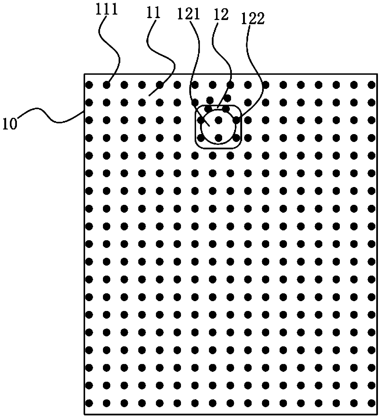
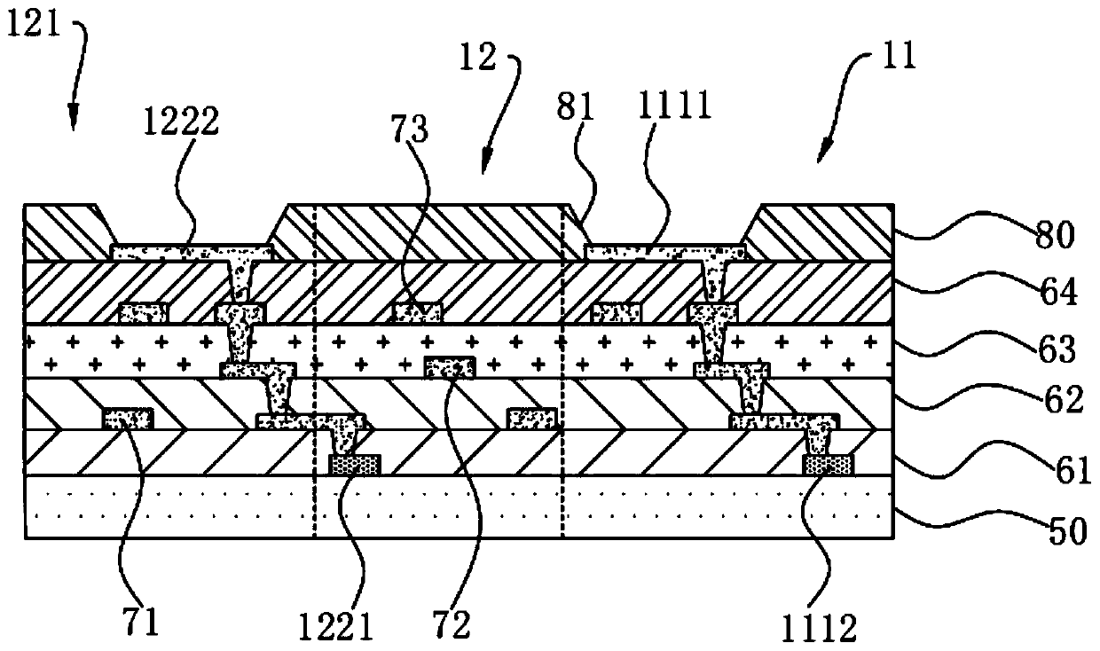
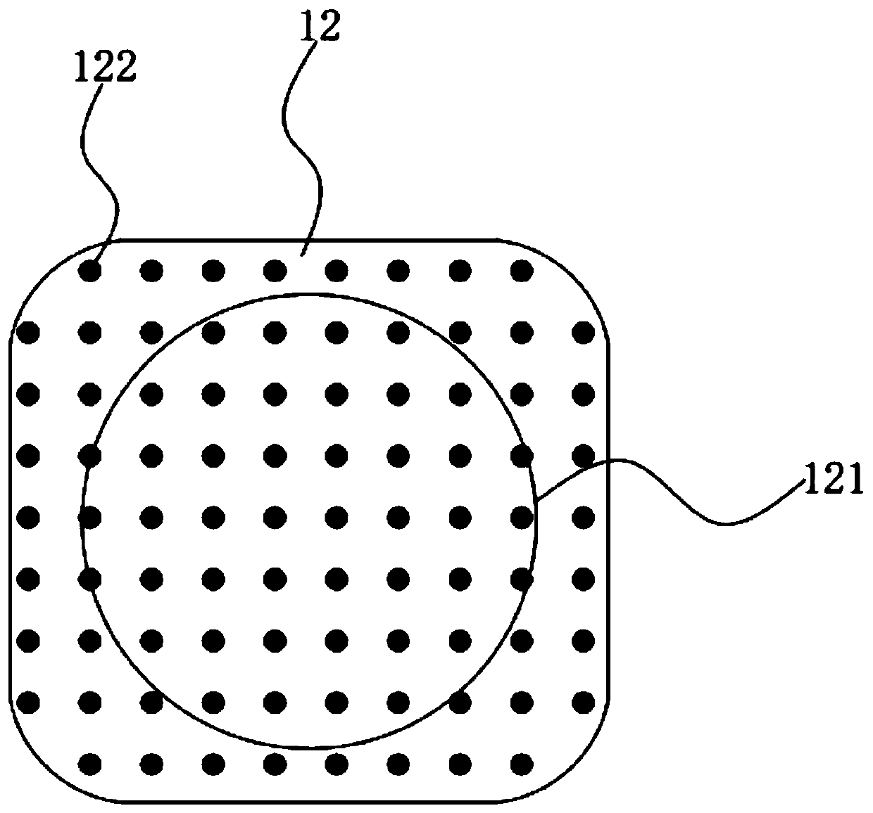
[0037] A display device such as figure 1 As shown, the display device includes a display panel 1...


PUM

PropertyMeasurementUnit
Areaaaaaaaaaaa

Abstract

A display device includes a display panel including a main display area and a function additional area, at least a portion of the function additional area being surrounded by the main display area; wherein a plurality of first pixels are arranged in the function additional area, at least one light-transmitting area is arranged in the function additional area, and the area of each light-transmitting area is larger than or equal to 0.32 square millimeter. By reasonably setting the shape and area of the light-transmitting area and limiting the area of the first anode located in the light-transmitting area, it is guaranteed that the function additional area can be used for displaying images, and therefore the display panel can show the full-screen display effect and can also be used for installing a camera and other photosensitive elements, and the user experience is improved.

Description

technical field [0001] The present invention relates to the field of display technology, in particular to a display device. Background technique [0002] In the design of an OLED display panel using an under-screen camera, in order to increase the light transmittance at the camera area on the display panel, a laser laser process is used to dig holes in the camera area. [0003] In the design of OLED display panels, how to have both camera and display functions in the camera area has always been a difficult problem. At present, setting the display function in the camera area will greatly reduce the light transmittance of the camera area, which will greatly affect the camera function of the camera area and affect user experience. Contents of the invention [0004] The present invention provides a display device to solve the technical problem that in the existing OLED display panel using an under-display camera, no picture is displayed in the camera area, the effect of full-...

Claims


Application Information

Patent Timeline
IPC IPC(8): H01L51/52H01L27/32G09G3/3208
CPCG09G3/3208H10K59/10H10K59/35H10K50/813H10K50/85
Inventor 赵勇廖作敏陈涛
Owner WUHAN CHINA STAR OPTOELECTRONICS SEMICON DISPLAY TECH CO LTD
Learn More