Variable-rigidity reinforced pneumatic soft driver

A software driver and enhanced technology, which is applied in the direction of program-controlled manipulators, manufacturing tools, manipulators, etc., can solve problems such as poor stability, poor positioning accuracy of flexible drives, uncontrollable stiffness, etc., and achieve large bending deformation, safety and stability Good, the effect of reducing the size of the drive

Pending Publication Date: 2019-11-26
NANJING UNIV OF SCI & TECH
View PDF5 Cites 23 Cited by
  • Summary
  • Abstract
  • Description
  • Claims
  • Application Information

AI Technical Summary

Benefits of technology

This patented technology uses an improved design for vehicles called compound arms. These arm parts are designed without any reinforcement elements like wires inside them, making their overall weight lighter than traditional designs while still maintaining strength and flexibility. They also allow for more accurate movements due to its unique shape. Overall, this new design improves vehicle performance and efficiency.

Problems solved by technology

This patented technical problem addressed in this patents relates to improving the functionality and precision of conventional hydraulically expandable or contractable actuators while maintaining their strength against external forces such as tensiles. These issues include limited displacement capabilities, difficulty controllably achieving multiple levels of movement, insensitive torque, and lack of feedback during operation.

Method used


Image

  • Variable-rigidity reinforced pneumatic soft driver
  • Variable-rigidity reinforced pneumatic soft driver
  • Variable-rigidity reinforced pneumatic soft driver

Examples


Embodiment Construction

[0028] The present invention will be described in further detail below in conjunction with the accompanying drawings.

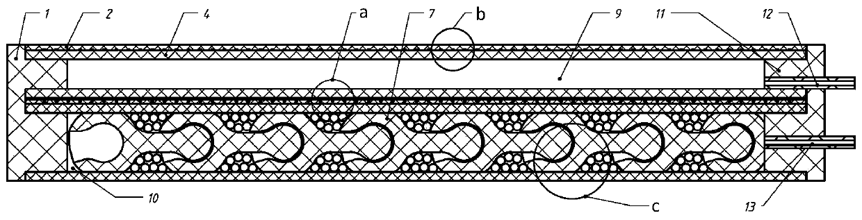
[0029] combine Figure 1 to Figure 13 , the present invention is a variable stiffness enhanced pneumatic software driver, the basic idea of ​​the present invention is to use compressed air to drive and vacuumize for stiffness control.

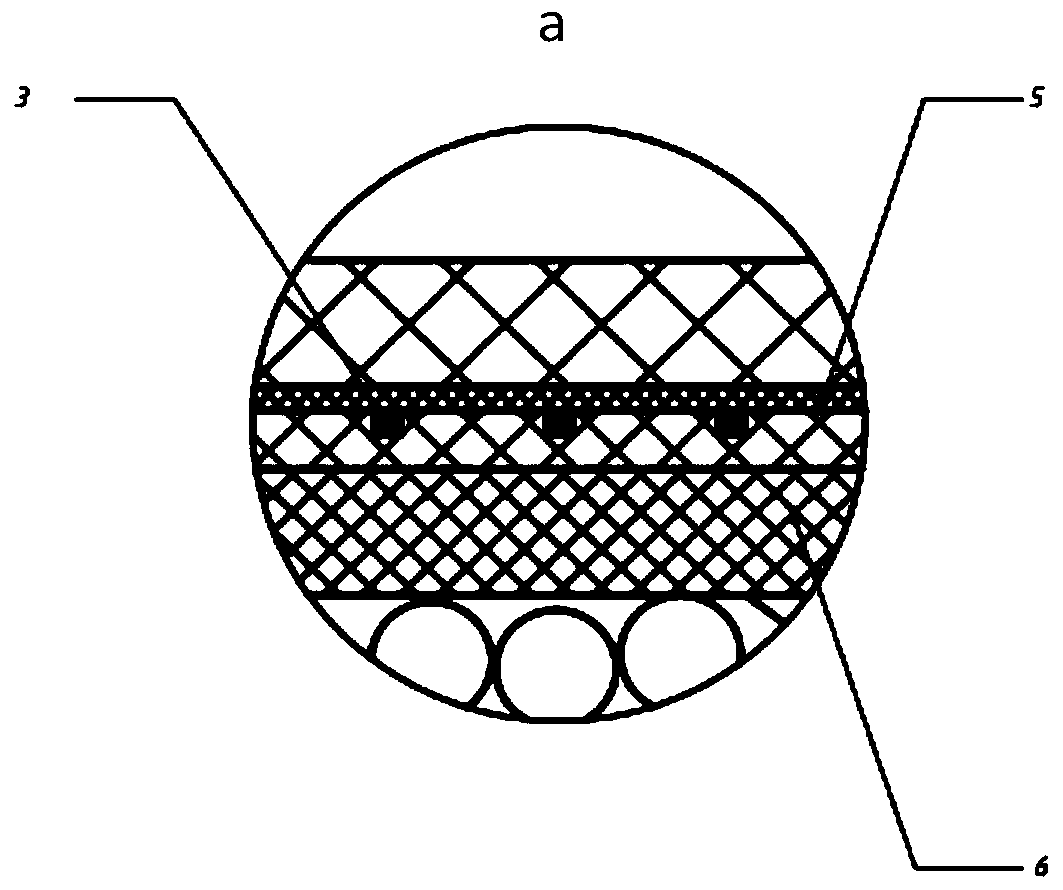
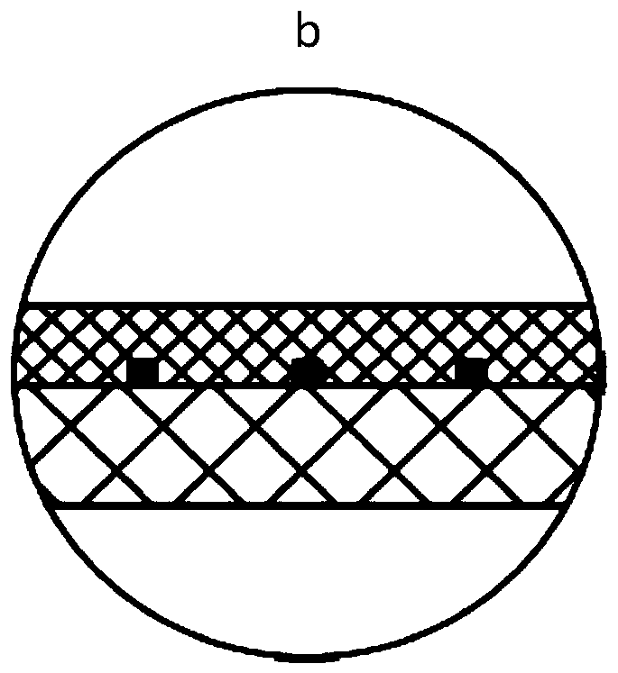
[0030] combine Figure 1 to Figure 4, a variable stiffness enhanced pneumatic software driver includes a front cover 1, a skin layer 2 outside the driving cavity, a filament 3, an inner core 4 in the driving cavity, an unstrained layer 5, a rigidity adjustment cavity inclusion 6, and a rear end cover 11 , air source inlet duct 12, air source outlet duct 13, some endoskeletons 7 and some particle spheroids 8. The inner core 4 of the drive cavity is a long tube, the inclusion 6 of the stiffness adjustment cavity is a square tube, the non-strained layer 5 is braided, and the unstrained layer 5 is pasted on the bottom surface of...


PUM


Abstract

The invention discloses a variable-rigidity reinforced pneumatic soft driver. A non-strain layer is pasted to the bottom face of a drive cavity inner core, and an initial drive cavity inner core is formed. The periphery of the initial drive cavity inner core is wrapped by thin wires on the top face and the bottom face of the initial drive cavity inner core. A drive cavity outer packaging skin layer is arranged on the outer sides of the thin wires to achieve packaging, and a packaged drive cavity is formed. The bottom plane of the drive cavity is pasted to the top face of a rigidity adjusting cavity wrapping body, and the two ends of the drive cavity are sealed by a front end cover and a rear end cover correspondingly. A drive gas cavity is formed in the sealed drive cavity inner core. A variable-rigidity adjusting gas cavity is formed in the rigidity adjusting cavity wrapping body. Multiple endoskeletons are arranged in the variable-rigidity adjusting gas cavity, and particle spheres are distributed in the variable-rigidity adjusting gas cavity and between the adjacent endoskeletons. A gas source gas inlet guide pipe stretches into the drive gas cavity from the rear end cover, compressed air enters the drive gas source through the gas source guide pipe, a gas source gas outlet guide pipe stretches into the variable-rigidity adjusting gas cavity from the rear end cover, and thevariable-rigidity adjusting gas cavity is vacuumized through the gas source guide pipe.

Description


Claims


Application Information

Patent Timeline
Owner NANJING UNIV OF SCI & TECH
Why Eureka
Try Eureka