Steering device

A steering device and steering angle technology, which is applied to steering mechanisms, steering rods, electric steering mechanisms, etc., can solve the problems of unverified reliability and high technical difficulty, and achieve the effect of reducing requirements and simplifying the parking process.

Active Publication Date: 2021-03-19
莫天德
View PDF10 Cites 0 Cited by
  • Summary
  • Abstract
  • Description
  • Claims
  • Application Information

AI Technical Summary

Problems solved by technology

[0003] However, the four-wheel independent steering system based on the steering-by-wire technology has the following disadvantages: the steering-by-wire technology is not yet mature, and its reliability has yet to be verified, and it has not yet reached the level where it can be safely promoted and applied on vehicles; In addition to the obvious high reliability requirements, the coordinated control of the kinematics and dynamics of the wheels on both sides is also extremely high, which is necessary for the normal driving of the vehicle, and the low-speed steering is only a very short process in the use of the vehicle, that is, In order to achieve higher but not commonly used low-speed steering performance, the technical difficulty of the steering system has been significantly increased. Although the disclosed technical solutions have shown fascinating and unique performance, their technical difficulty is also significant, so it is difficult put into actual use in the near future or in a period of time in the future

Method used


Image

  • Steering device
  • Steering device
  • Steering device

Examples


Embodiment Construction

[0035] In order to understand the technical content of the present invention more clearly, the following examples are given in detail. It should be understood that the examples are only used to illustrate the present invention, not to limit the present invention.

[0036] [Fundamental]

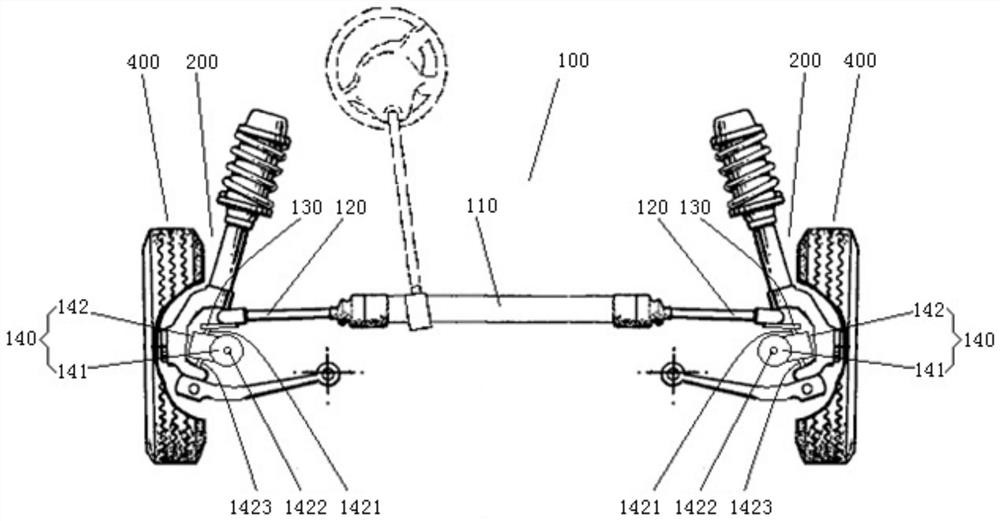
[0037] like figure 1 As shown, the steering device 100 includes: a steering gear 110; a first tie rod 120 connected to the left and right ends of the steering gear 110; a first steering arm 130 connected to the first tie rod 120; a wheel steering angle variable mechanism 140, Comprising a wheel steering motor 141 and a wheel steering angle superimposing mechanism 142, the wheel steering angle superimposing mechanism 142 is arranged in the suspension 200, has a first input shaft 1421, a second input shaft 1422 and an output shaft 1423, the first input shaft 1421 and the second A steering arm 130 is connected, the wheel steering motor 141 drives the second input shaft 1422, the rotation angle ...


PUM


Abstract

The invention provides a steering device which comprises a steering machine, first transverse pull rods connected to the left end and the right end of the steering machine respectively, first steeringarms connected with the first transverse pull rods respectively and wheel steering angle variable mechanisms; each wheel steering angle variable mechanism comprises a wheel steering motor and a wheelsteering angle superposition mechanism; each wheel steering angle superposition mechanism is installed in a suspension and is provided with a first input shaft, a second input shaft and an output shaft; each first input shaft is connected with the corresponding first steering arm; each wheel steering motor drives the corresponding second input shaft; steering angle input of each first input shaftand steering angle input of the corresponding second input shaft are synthesized into steering angle output of an output shaft; and the output shafts drive the wheels to steer respectively. For the steering device, the wheel steering angle superposition mechanism is installed in the suspension nearby each wheel, the output shaft of each wheel steering angle superposition mechanism drives the corresponding wheel to steer, the corresponding wheel steering motor drives the wheel to achieve a steering angle up to 90 degrees, and a parking process is simplified; and each wheel steering motor is further connected with the corresponding steering machine, so that after steering angle input of the wheel steering motors and steering angle input of the steering machine are subjected to superpositionduring normal running, the wheels are driven to steer, and the requirements for a steering control system are lowered.

Description

technical field [0001] The present invention relates to a steering device for steering a wheel around a kingpin axis, in particular to an improved scheme of the steering device with a steering angle of up to 90 degrees. Background technique [0002] ROMO (Schaub, A.; Brembeck, J.; HO, L.M.; Sattzger, C.; Tobolar, J.; Bals, J.; Hirzinger: ROMO–The Robotic Electric Vehicle. In: 22nd IAVSD International Symposium on Dynamics of Vehicle on Roads and Tracks, 2011) is a 4WID / 4WIS (four-wheel independent drive / four-wheel independent steering) vehicle, which uses four in-wheel motors to independently drive the wheels supported by the double-wishbone suspension and is installed on the upper cross The four steering motors above the arm drive the steering knuckles independently, so that the maximum steering angle of the wheels reaches 90°, so in-situ steering, fixed-point steering and lateral driving can be realized, which significantly improves the vehicle maneuverability. [0003] H...

Claims


Application Information

Patent Timeline
Patent Type & Authority Patents(China)
IPC IPC(8): B62D5/04B62D7/15B62D7/18
CPCB62D5/0418B62D7/15B62D7/18
Inventor 莫天德
Owner 莫天德
Why Eureka
Try Eureka