Inspection well flexible interface structure
A flexible interface and inspection well technology, which is used in drainage structures, pipes/pipe joints/pipes, waterway systems, etc., can solve problems such as dry cracking, poor construction quality, and general cement mortar sealing, and achieve increased sealing, The effect of improving work efficiency
- Summary
- Abstract
- Description
- Claims
- Application Information
AI Technical Summary
Problems solved by technology
Method used
Image
Examples
Embodiment 1
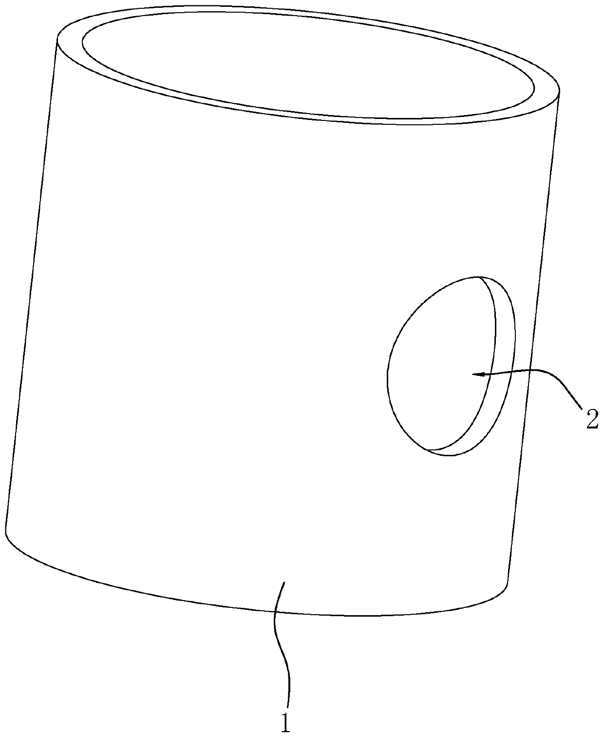
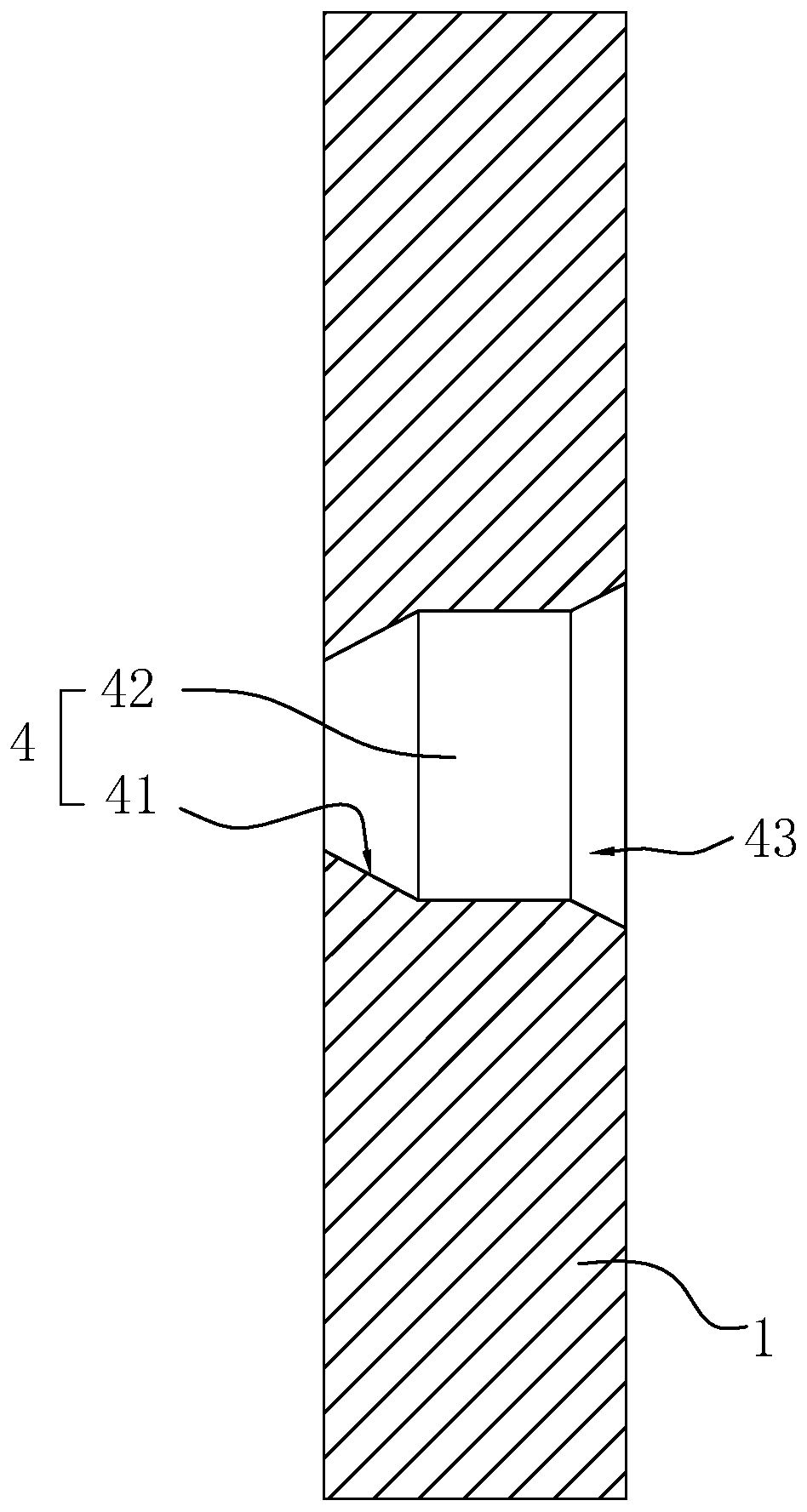
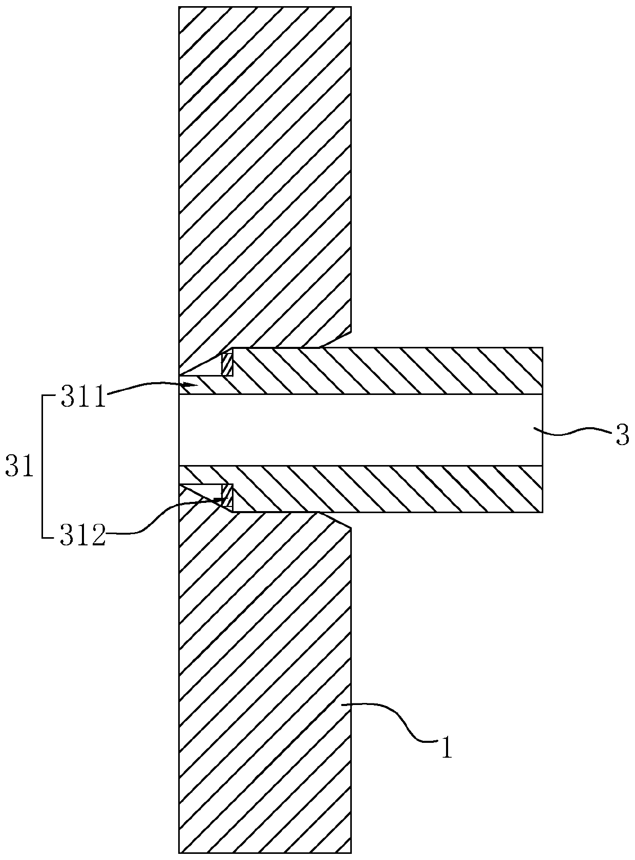
[0040] Embodiment one: refer to figure 2 , is a kind of inspection well flexible interface structure disclosed in the present invention, the reserved hole 2 of the inspection well 1 is provided with a socket 4, and the socket 4 is provided with an inclined surface 41 along the direction away from the side wall of the inspection well 1, parallel segment 42 and a flaring segment 43 that expands the diameter outward, and the flaring segment 43 is arranged at the entrance of the socket 4 . Such as figure 2 and image 3 As shown, the end of the drain pipe 3 is provided with a socket 31. The socket 31 includes a circle of grooves opened around the end of the drain pipe 3 and a circle of flanges 311 formed after the grooves are opened. The flange 311 is sleeved with The first sealing ring 312, the first sealing ring 312 is made of rubber, and the cross section of the first sealing ring 312 is square.
[0041] When installing, insert the socket 31 sleeved with the first sealing r...
Embodiment 2
[0042] Embodiment 2: An inspection well flexible interface structure, the difference from Embodiment 1 is that, as Figure 4 As shown, at the junction of the parallel section 42 and the inclined surface 41, a circle of clamping grooves 44 perpendicular to the axial direction of the socket 4 is provided, as Figure 5 As shown, after the first sealing ring 312 is set on the socket 31, the diameter of the first sealing ring 312 is slightly larger than the socket 31. During the process of inserting the socket 31 into the socket 4, the parallel section 42 is extruded to make the first The sealing ring 312 is squeezed in after being compressed and deformed, and the outer wall of the first sealing ring 312 snaps into the slot 44 after being put in place. The slot 44 can make the first sealing ring 312 be better fixed in the socket 4, thereby This makes the installation between the socket 31 and the socket 4 more stable, and the sealing performance is better.
Embodiment 3
[0043] Embodiment 3: An inspection well flexible interface structure, the difference from Embodiment 2 is that, as Figure 6 As shown, the flange 311 of the socket 31 is provided with an inclined extrusion surface 3111 corresponding to the inclined surface 41 of the socket 4, as Figure 7 As shown, when the socket 31 is plugged into the socket 4, the inclined extrusion surface 3111 can be in conflict with the inclined surface 41, thereby filling the gap between the inclined surface 41 and the socket 31, so that the socket 31 and the socket 4 can be more closely matched. Tighter, better sealing.
PUM
 Abstract
Description
Claims
Application Information
 - R&D
- Intellectual Property
- Life Sciences
- Materials
- Tech Scout
- Unparalleled Data Quality
- Higher Quality Content
- 60% Fewer Hallucinations
Browse by: Latest US Patents, China's latest patents, Technical Efficacy Thesaurus, Application Domain, Technology Topic, Popular Technical Reports.
© 2025 PatSnap. All rights reserved.Legal|Privacy policy|Modern Slavery Act Transparency Statement|Sitemap|About US| Contact US: help@patsnap.com


