
Displacement amplifying device and displacement amplifier

A displacement amplifier and displacement amplifying technology, applied in the direction of measuring devices, instruments, etc., can solve the problem that displacement amplifiers are not suitable for application in some devices, etc.

Inactive Publication Date: 2019-11-26
PREMTEK INT
View PDF7 Cites 0 Cited by
  • Summary
  • Abstract
  • Description
  • Claims
  • Application Information

AI Technical Summary

Problems solved by technology

However, the action path of the displacement output point of the existing displacement amplifier is a circular arc, which makes the existing displacement amplifier not suitable for application in some devices

Method used


Image

  • Displacement amplifying device and displacement amplifier
  • Displacement amplifying device and displacement amplifier
  • Displacement amplifying device and displacement amplifier

Examples


Embodiment 1

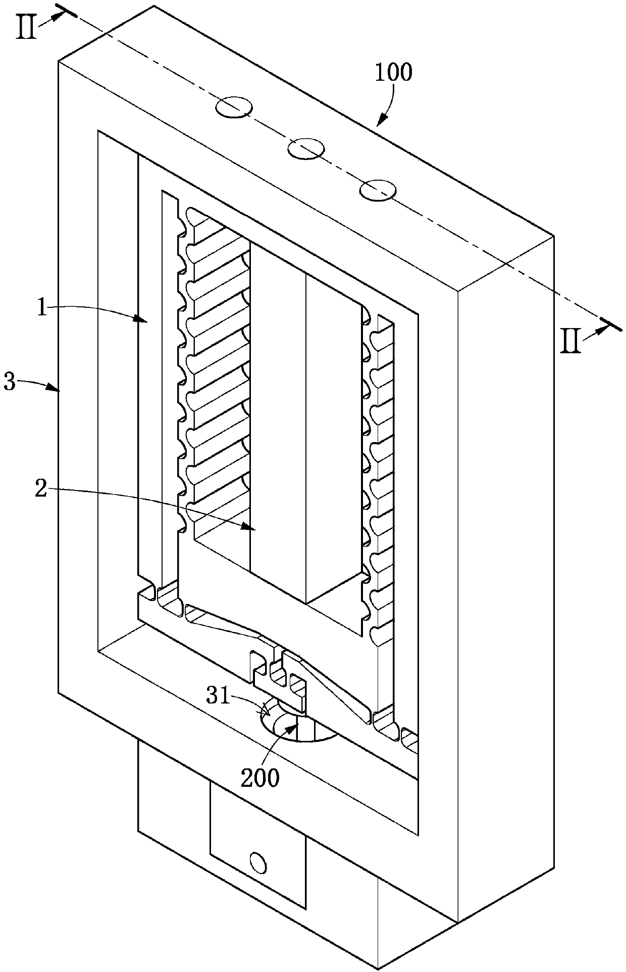
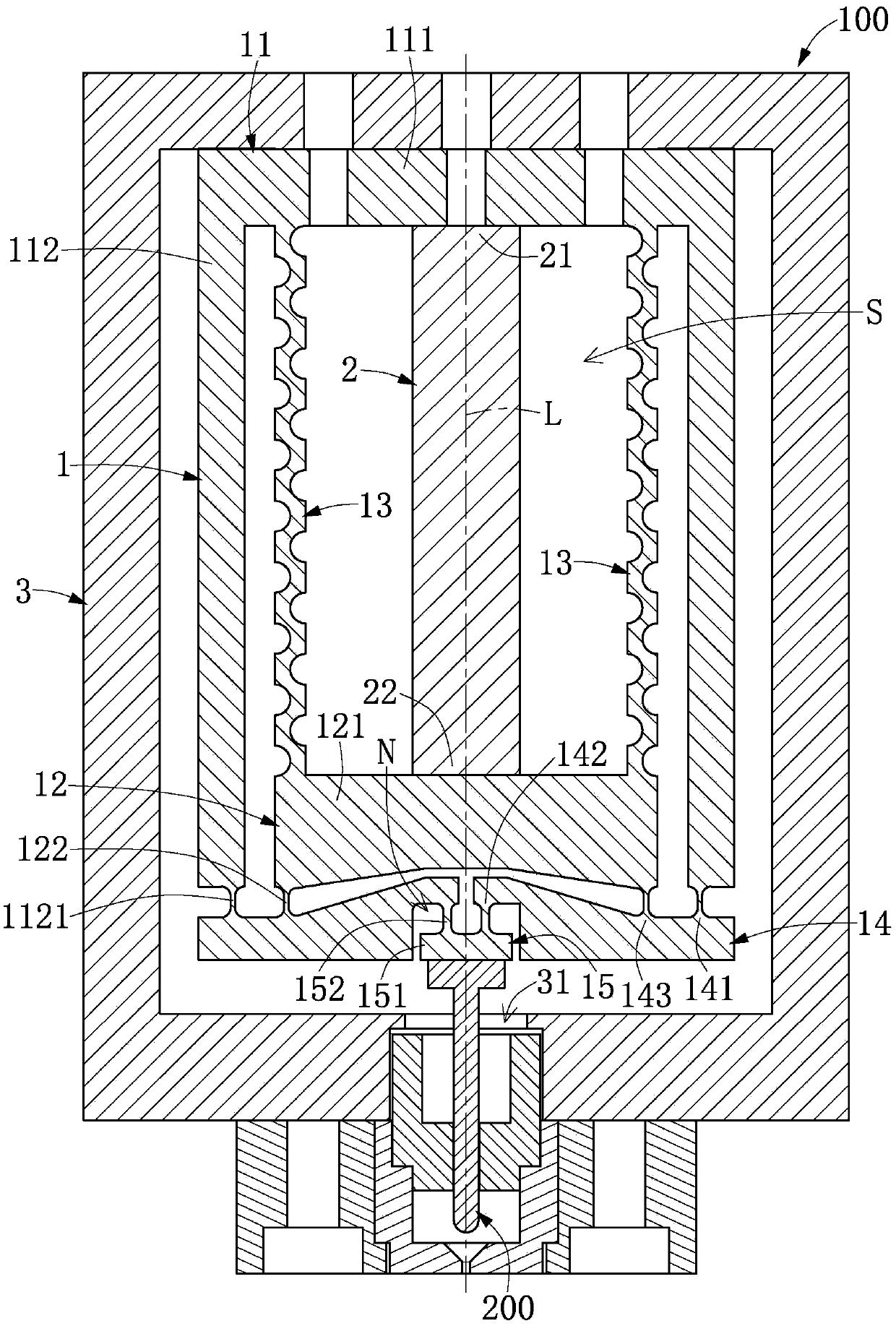
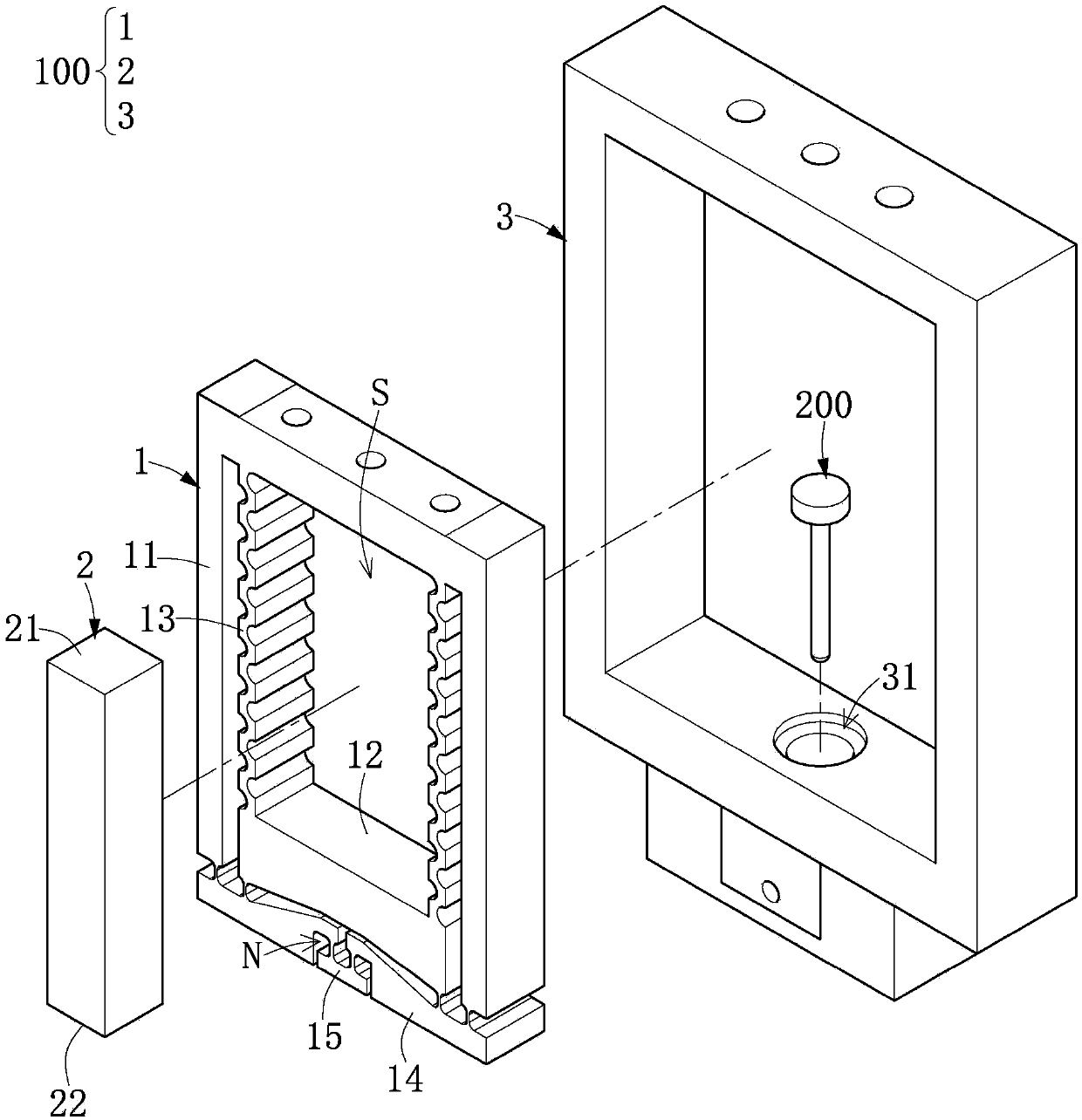
[0032] Such as Figure 1 to Figure 10 As shown, it is Embodiment 1 of the present invention. This embodiment discloses a displacement amplifying device 100, which is suitable for use in equipment that needs to use displacement to open and close the entrance, such as: a jetting valve (JettingValve) in dispensing equipment, but the application of the displacement amplifying device 100 of the present invention does not use This is the limit. Wherein, the displacement amplifying device 100 includes a displacement amplifier 1 , an actuator 2 mounted on the displacement amplifier 1 , and an outer frame 3 installed outside the displacement amplifier 1 and the actuator 2 .

[0033] It should be noted that the displacement amplifier 1 of this embodiment is illustrated with the actuator 2 and the outer frame 3 , but the present invention is not limited thereto. For example, in other embodiments not shown in the present invention, the displacement amplifier 1 can also be used alone (su...

Embodiment 2

[0059] Such as Figure 11 and Figure 12 As shown, it is Embodiment 2 of the present invention. This embodiment is similar to the above-mentioned Embodiment 1, so the similarities between the two embodiments will not be repeated. The difference between this embodiment and Embodiment 1 mainly lies in: The displacement amplifier 1 of the embodiment may be a multi-piece combination, that is to say, the displacement amplifier 1 is not an integrally formed component. Wherein, the multi-piece combination adopted by the above-mentioned displacement amplifier 1 may be connected by fitting, welding or screw locking, which is not limited by the present invention.

Embodiment 3

[0061] Such as Figure 13As shown, it is the third embodiment of the present invention. This embodiment is similar to the above-mentioned embodiment one or embodiment two, so the same place of the above-mentioned embodiment will not be repeated, and this embodiment is compared with embodiment one (or implementation Example 2) The difference mainly lies in that the displacement amplifier 1 of this embodiment is 120 degrees rotationally symmetrical with respect to the linear direction L. Example for three.


PUM


Abstract

The invention discloses a displacement amplifying device and a displacement amplifier. The displacement amplifier comprises an inner frame, a displacement input part, a plurality of amplifying mechanisms and a displacement output part, wherein the inner frame comprises a base part and a plurality of supporting parts connected with the base part, and the displacement input part and the base part are oppositely arranged; each amplifying mechanism comprises a rotating fulcrum, a stress point and a force application point, the rotating fulcrums of the plurality of amplifying mechanisms are connected to the plurality of supporting parts respectively, and the stress points are connected to the displacement input part; and the displacement output part is connected to the force application pointsof the plurality of amplifying mechanisms. When the displacement input part receives an external force and moves by a first distance in the linear direction, the displacement input part forces the plurality of amplifying mechanisms to rotate so that the plurality of force application points rotate, and then jointly drives the displacement output part to move by a second distance greater than the first distance in the linear direction. Accordingly, the displacement amplifier ensures that the displacement of the displacement output part of the displacement amplifier can be linear and the displacement amplifier has an amplification effect.

Description

technical field [0001] The invention relates to a displacement amplifying device and a displacement amplifier, in particular to a displacement amplifying device and a displacement amplifier which amplify displacement along a linear direction. Background technique [0002] Existing displacement amplifiers often use a single fulcrum pivoting method, so that the moment arm of the displacement output point relative to the fulcrum is longer than the moment arm of the displacement input point relative to the above fulcrum, so as to achieve the effect of displacement amplification. However, the motion path of the displacement output point of the existing displacement amplifier is a circular arc, so that the existing displacement amplifier is not suitable for application in some devices. [0003] Therefore, the inventor of the present invention believes that the above-mentioned defects can be improved, especially devoted himself to research and combined with the application of scien...

Claims


Application Information

Patent Timeline
Patent Type & Authority Applications(China)
IPC IPC(8): G01B21/02
CPCG01B21/02
Inventor 林武郎石玉光陈世敏颜千智吴炫亿
Owner PREMTEK INT
Learn More