Magnetic type self-switching infrared monitor

A self-switching and monitoring technology, applied in CCTV systems and other directions, can solve the problems of poor shooting effect, insufficient light, fixed infrared switching time, etc., to achieve the effect of reducing impact, strong flexibility, and improving shooting clarity

Active Publication Date: 2019-11-29
安徽卓呈科技有限公司
View PDF10 Cites 0 Cited by
  • Summary
  • Abstract
  • Description
  • Claims
  • Application Information

AI Technical Summary

Problems solved by technology

[0006] The purpose of the present invention is to provide a magnetic self-switching infrared monitor that can be automatically adjusted according to the temperature in view of the problem that the infrared switching time of the existing monitor is fixed, which may cause poor shooting effects caused by insufficient light

Method used


Image

  • Magnetic type self-switching infrared monitor
  • Magnetic type self-switching infrared monitor
  • Magnetic type self-switching infrared monitor

Examples


Embodiment 1

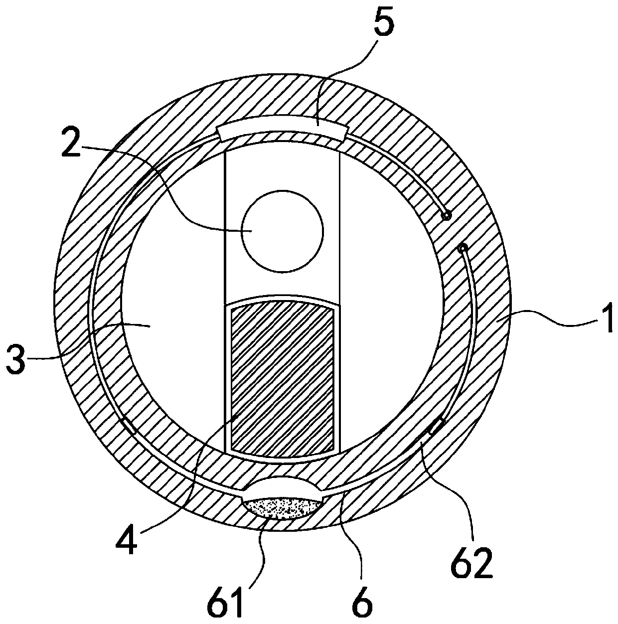
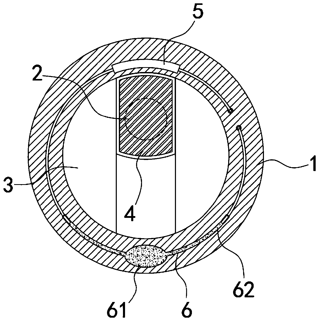
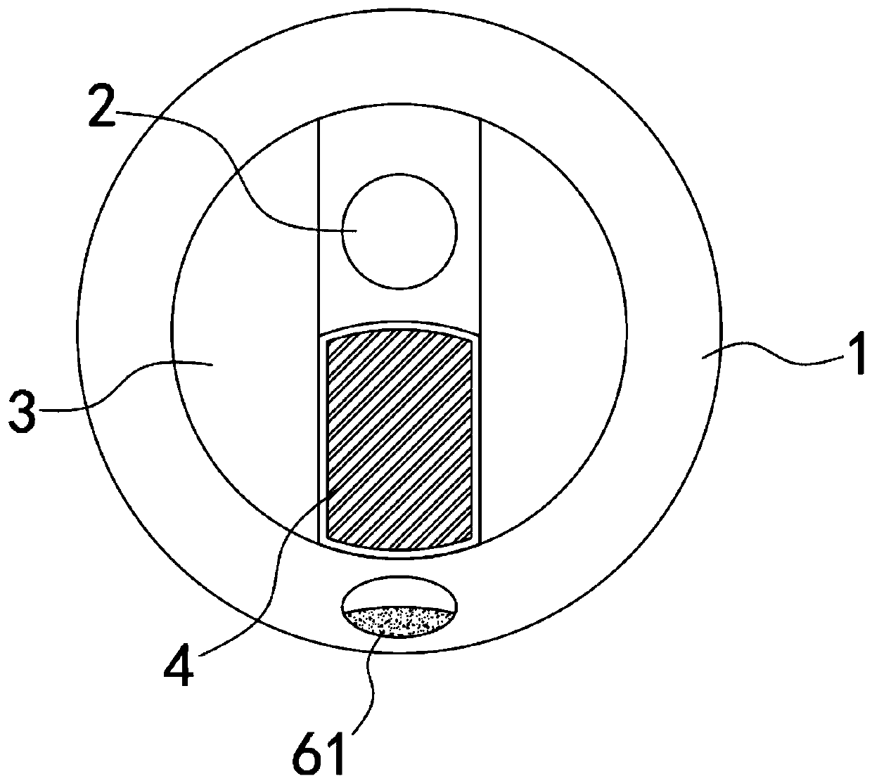
[0020] Such as Figure 1-3 As shown, a magnetic self-switching infrared monitor includes a cylindrical housing 1, and a monitoring head 2 is installed on the upper half of the housing 1, that is, the monitoring head 2 is arranged on the axis of the cylindrical housing 1 In the above part, both sides of the monitoring head 2 are provided with arc-shaped blocks 3, a vertical slideway is formed between the two arc-shaped blocks 3, and the infrared cut-off plate 4 is slidably connected in the slideway, and the frame of the infrared cut-off plate 4 Using magnetic material, under the initial state, under the action of gravity of the infrared cut-off plate 4, the infrared cut-off plate 4 is at the lowermost side of the slideway (such as figure 1 As shown), at this time, the monitoring head 2 is directly exposed to the outside, which can meet the requirement that the monitoring head 2 has enough light at night or on cloudy days. The upper part of the housing 1 is embedded with an elec...

Embodiment 2

[0024] Such as Figure 4 As shown, the difference between this embodiment and Embodiment 1 is that the temperature control switch 6 includes a slot arranged on the upper part of the housing 1, and a transparent block 63 is fixedly connected in the slot, and the edge of the transparent block 63 is connected with the housing 1. The outer edge of the transparent block 63 is matched to form a complete cylinder. The cross-section of the transparent block 63 is in the shape of a shuttle that is convex on both sides and pointed at both ends. An upward curved, arc-shaped, A flat vacuum chamber 64 containing mercury, and conductive contacts embedded in the upper end surfaces of both sides of the vacuum chamber 64 .

[0025] In this embodiment, when external strong light passes through the transparent block 63 and irradiates the mercury to increase its temperature, the mercury expands when heated and will cover the vacuum cavity 64 and form a concave mirror. On the one hand, the concave...


PUM


Abstract

The invention belongs to the field of monitoring equipment in particular to a magnetic type self-switching infrared monitor. The monitor comprises a cylindrical shell. A monitoring head is mounted atthe upper half part of the shell. Arc-shaped blocks are arranged on the two sides of the monitoring head. A slide way in the vertical direction is formed between the two arc-shaped blocks. An infraredcut-off plate is connected into the slide way in a sliding manner,. A frame of the infrared cut-off plate is made of a magnetic material. An electromagnet is embedded in the upper portion of the shell, the electromagnet can attract the infrared cut-off plate to the uppermost side of the sliding way in the power-on state, so that the infrared cut-off plate can block external infrared rays outsidethe monitoring head, a temperature control switch is arranged on the shell, and the temperature control switch, the electromagnet and an external power source are coupled in series. The temperature control switch is arranged to control switching of the infrared cut-off plate, higher flexibility is achieved, automatic adjustment can be conducted according to weather conditions, the influence of infrared rays on the monitor is reduced to the maximum extent, and it can be guaranteed that the monitor has enough light incoming amount.

Description

technical field [0001] The invention belongs to the field of monitoring equipment, in particular to a magnetic self-switching infrared monitor. Background technique [0002] With the increasing popularity of closed-circuit surveillance in civil and commercial purposes, surveillance cameras are widely used in various fields to protect enterprise management and social security. Monitors are widely used in residential buildings, real estate villas, shopping malls, and financial offices. [0003] Infrared monitors on the market are generally equipped with infrared filters, which are used to filter infrared rays under strong sunlight, reduce interference to imaging, and improve shooting clarity. In addition, during use, filter switches are generally used Switch the filter, use the infrared cut-off filter during the day to restore the color; at night, use the fully transparent filter to increase the amount of light entering and improve the night vision effect. [0004] The exist...

Claims


Application Information

Patent Timeline
Patent Type & Authority Applications(China)
IPC IPC(8): H04N7/18
CPCH04N7/18
Inventor 王金鑫饶杨扬杨静
Owner 安徽卓呈科技有限公司
Why Eureka
Try Eureka