
Vehicle tyres having sipe in profile block element

A technology of pneumatic tires and tread blocks, which is applied to vehicle parts, tire parts, tire treads/tread patterns, etc., which can solve the problems of reduced stiffness of tread blocks and achieve the effect of improving driving behavior

Inactive Publication Date: 2019-11-29
CONTINENTAL REIFEN DEUTSCHLAND GMBH
View PDF16 Cites 0 Cited by
  • Summary
  • Abstract
  • Description
  • Claims
  • Application Information

AI Technical Summary

Problems solved by technology

However, an increase in the number of fine cuts directly leads to a decrease in the stiffness of the tread block

Method used


Image

  • Vehicle tyres having sipe in profile block element
  • Vehicle tyres having sipe in profile block element
  • Vehicle tyres having sipe in profile block element

Examples


Embodiment Construction

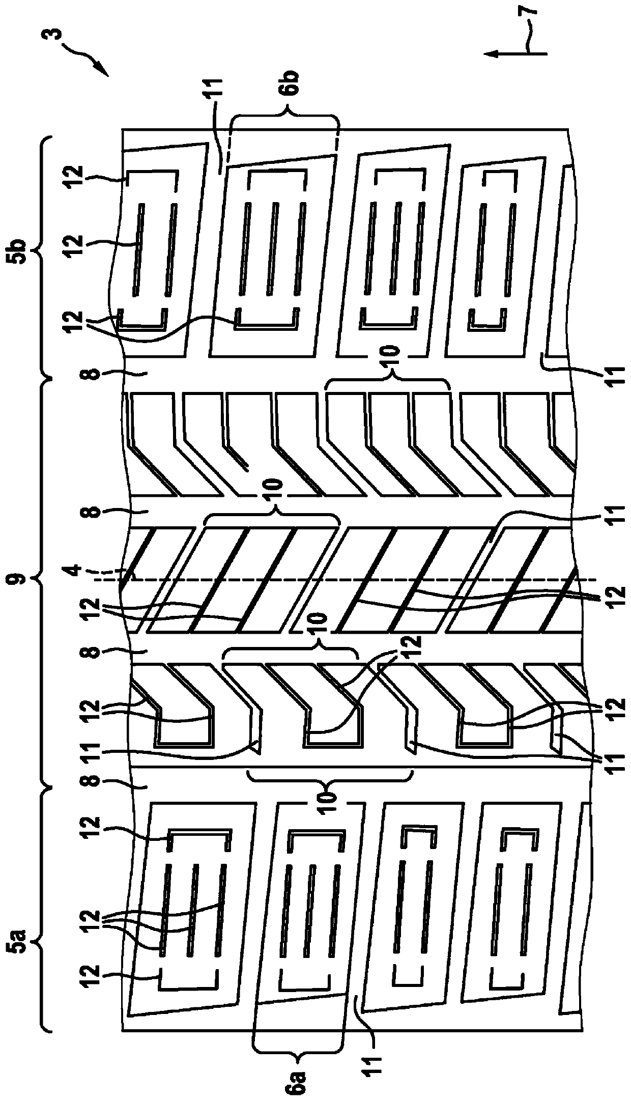
[0095] figure 1 A schematic representation of a tread 3 of a pneumatic tire for vehicles according to the invention according to a first embodiment is shown in plan view, wherein two shoulders 5a, 5b with rows of shoulder block units 6a, 6b are shown And a central tread region 9 with rows of central block units 10 . The tread 3 also has circumferential grooves 8 , transverse grooves 11 and fine incisions 12 . Furthermore, a tire apex 4 is shown in dashed form in the center of the tread 3 . figure 1 The fine cuts 12 in the shoulder block units 6a, 6b are spatially separated from the lateral grooves 11 and the circumferential grooves 8, while the fine cuts 12 in the central block unit 10 lead into Circumferential grooves 8.

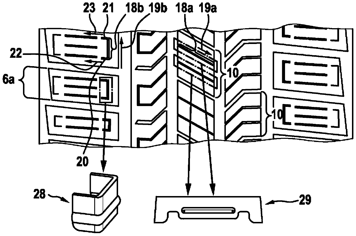
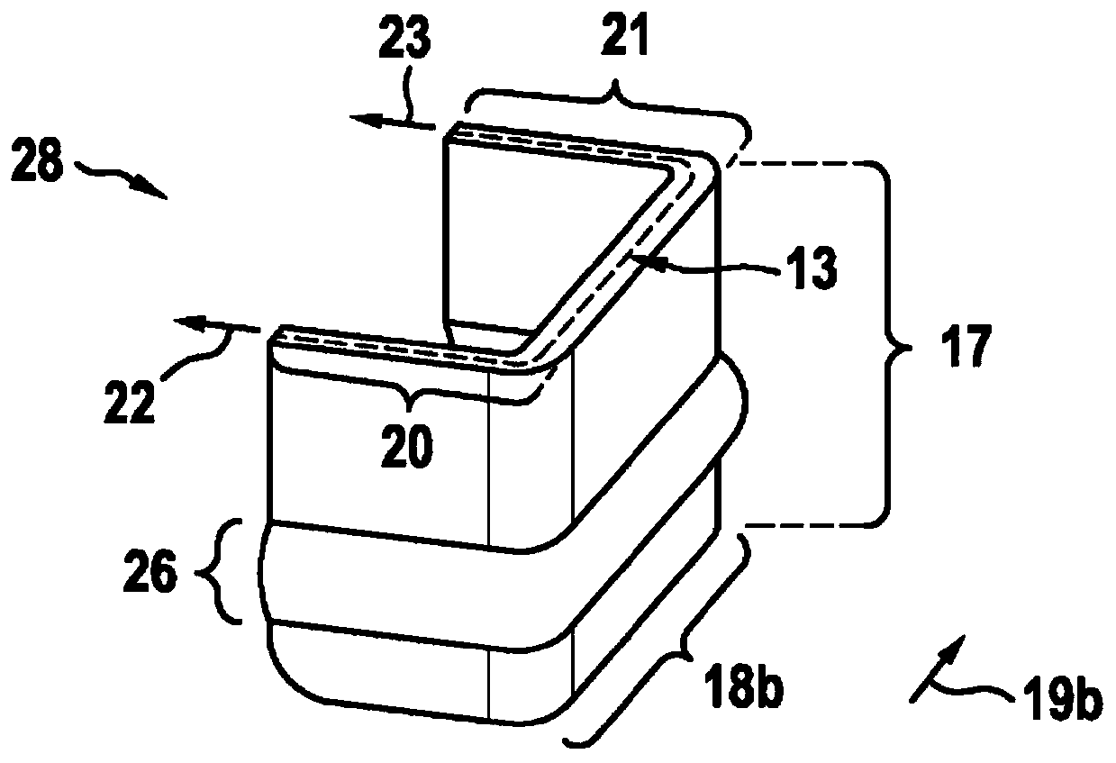
[0096] figure 2 A schematic representation of a tread 3 of a pneumatic tire for vehicles according to the invention in another embodiment is shown in top view, wherein additionally a laminate for the manufacture of fine cuts in a shoulder block unit ...


PUM


Abstract

The invention relates to a vehicle tyre having a tread with a contact surface, wherein the tread has rows of shoulder profile block elements running from a tyre crown to tyre shoulders, wherein the rows of shoulder profile block elements are separated from a central tread region having one or more rows of central profile block elements by circumferential grooves running in the circumferential direction, wherein, in the rows of shoulder profile block elements, individual shoulder profile block elements are separated from one another by transverse grooves, and wherein, in the row / s of central profile block elements, individual central profile block elements are separated from one another by transverse grooves, wherein at least one profile block element of all the shoulder profile block elements and the central profile block elements has at least one sipe, wherein the sipe has a total extension length LGES running parallel to the contact surface, characterised in that the sipe has a channel-shaped region in the form of a corrugation and with a channel length LR running parallel to the contact surface, wherein the channel-length LR corresponds to 20% to 100% of the total extension length LGES of the sipe.

Description

technical field [0001] The present invention relates to a vehicle pneumatic tire having a tread including a contact surface, wherein the tread has a plurality of rows of shoulder block units from the apex of the tire toward the shoulder, wherein the plurality of rows of shoulder block units are passed through The surrounding circumferential grooves in the circumferential direction are separated from the central tread area with one or more rows of central block units, wherein each shoulder block unit in the plurality of rows of shoulder block units is divided into The transverse grooves are separated from each other, and wherein each central block unit in the row or rows of central block units is separated from each other by a transverse groove, wherein by all of the shoulder block units At least one tread block unit formed with all these central tread block units has at least one thin cut, wherein the fine cut has a total extension length L extending parallel to the contact su...

Claims


Application Information

Patent Timeline
IPC IPC(8): B60C11/12B60C11/03
CPCB60C11/0306B60C11/1218B60C11/0304B60C11/0302B60C2011/0341B60C2011/0358B60C2011/1254
Inventor 马蒂亚斯·雅各布
Owner CONTINENTAL REIFEN DEUTSCHLAND GMBH
Learn More