Cleaning equipment

A technology for cleaning equipment and cleaning surfaces, which is applied in the field of machinery, and can solve problems such as round pipes getting stuck, obstacles stuck on obstacles, and sweeping robots that cannot cross over.

Pending Publication Date: 2019-12-03
SHENZHEN REECOO ELECTRONICS CO LTD
View PDF0 Cites 4 Cited by
  • Summary
  • Abstract
  • Description
  • Claims
  • Application Information

AI Technical Summary

Problems solved by technology

[0003] However, the existing sweeping robot also has certain defects. For example, in the prior art, when the sweeping robot executes the cleaning command, it often encounters obstacles, especially circular obstacles, square obstacles or other irregular Obstacles, etc., the sweeping robot cannot cross the obstacle or it is easy to get stuck on the obstacle for a long time and cannot escape
The common situation is that the circular obstacle is a circular tube, and the circular tube is stuck on the driving wheel, and the sweeping robot cannot get out of the trap, causing the machine to alarm and stop working

Method used


Image

  • Cleaning equipment
  • Cleaning equipment
  • Cleaning equipment

Examples


Embodiment 1

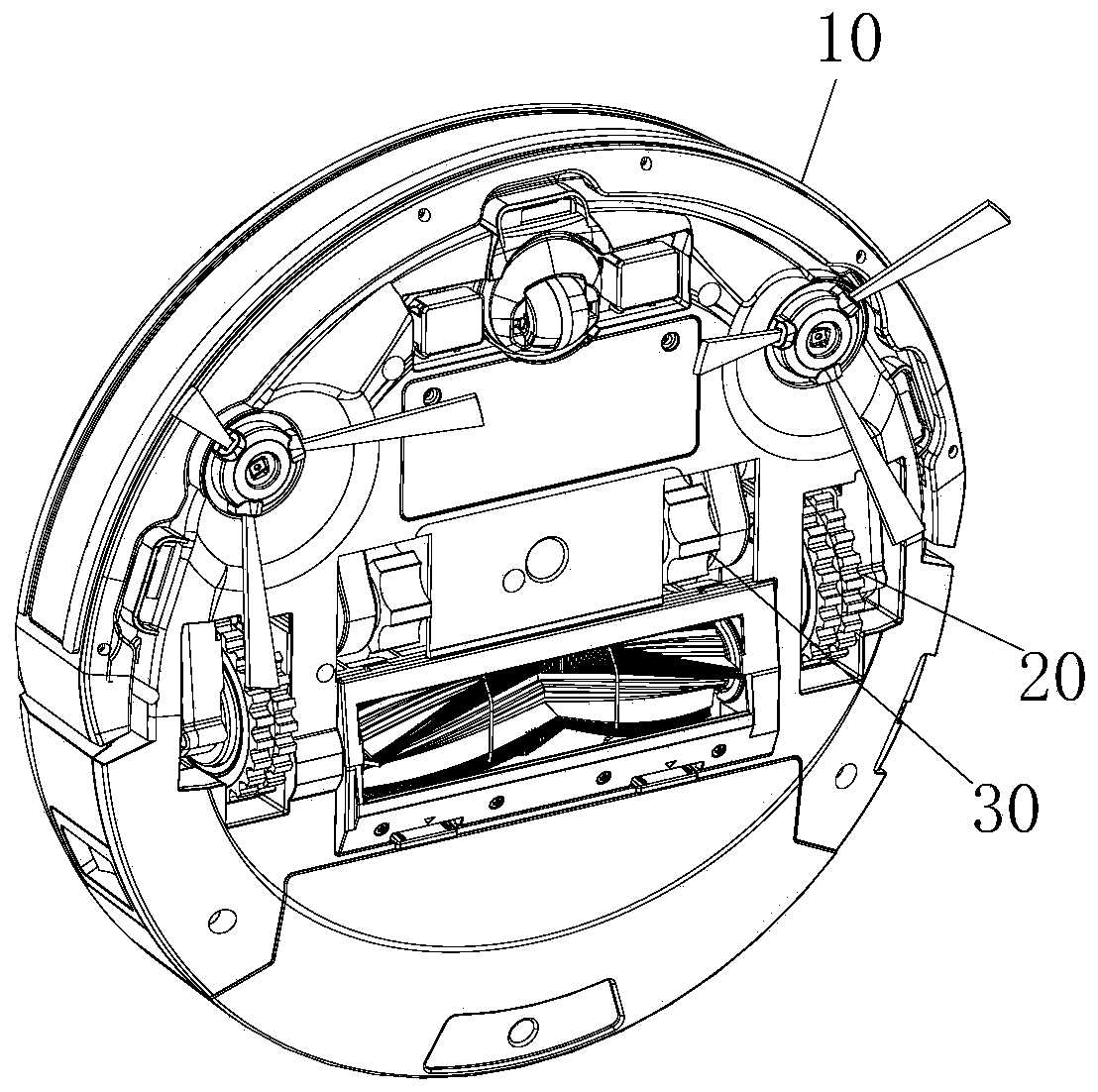
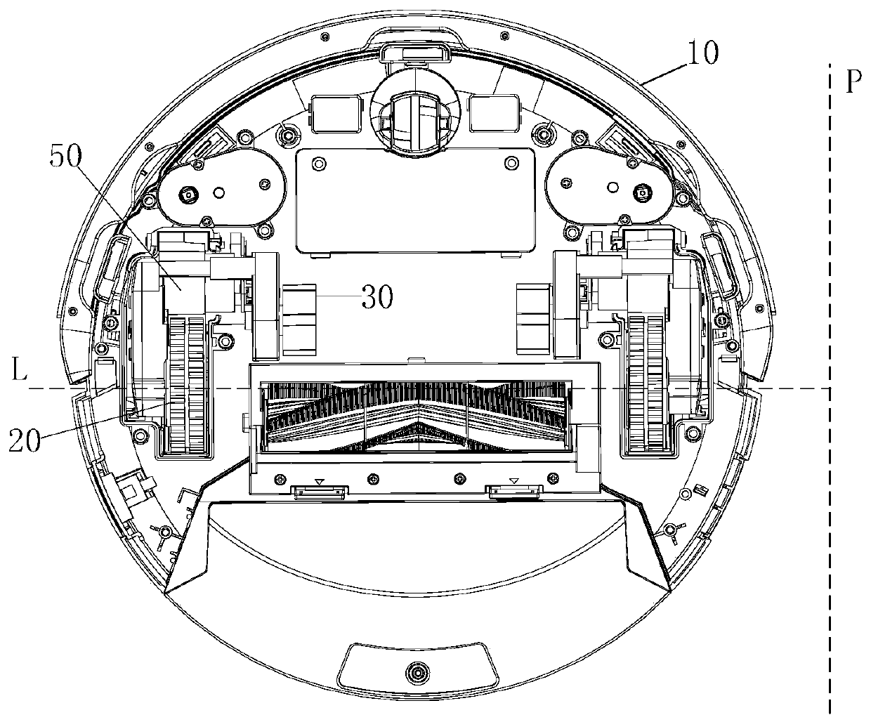
[0055] figure 1 It is a schematic diagram of the three-dimensional structure of the bottom view of the cleaning equipment provided by an embodiment of the present invention, figure 2 It is a stereoscopic structural diagram of another bottom view of the cleaning equipment provided by an embodiment of the present invention, image 3 A schematic diagram of the cross-sectional structure of the cleaning equipment provided by an embodiment of the present invention, such as Figure 1 to Figure 3 shown.

[0056] In one embodiment of the present invention, a cleaning device is provided, including: a main body 10 , a driving wheel 20 and an auxiliary rotating member 30 .

[0057] Wherein, the driving wheel 20 and the auxiliary rotating member 30 are both arranged on the main body 10 . The auxiliary rotating member 30 is suspended. The driving wheel 20 and the auxiliary rotating member 30 have projections on a plane perpendicular to the rotation center of the driving wheel 20 , and ...

Embodiment 2

[0102] see Figure 1 to Figure 6 Correspondingly, the embodiment of the present invention also provides a cleaning device, including: a main body 10 , a driving wheel 20 and an auxiliary rotating member 30 .

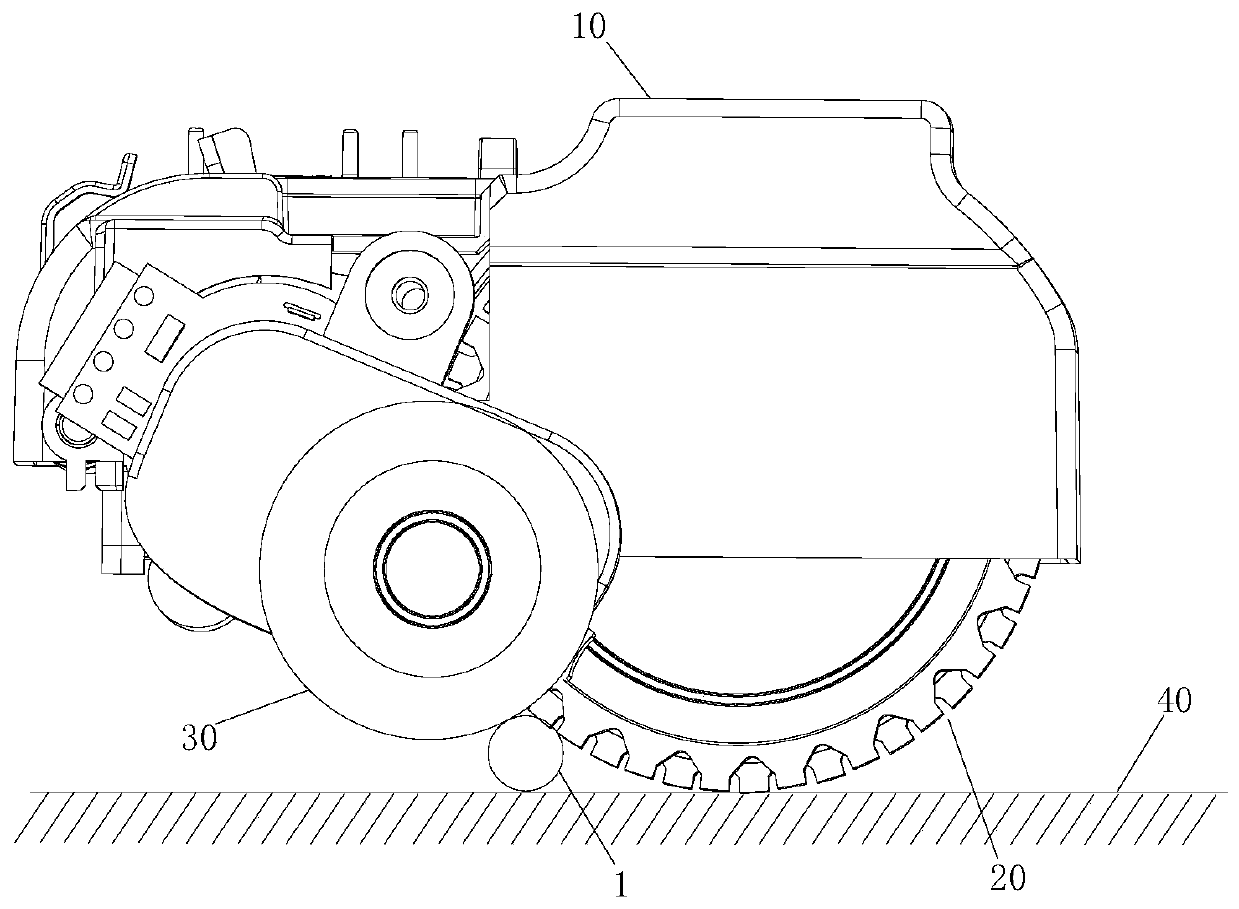
[0103] Wherein, the driving wheel 20 and the auxiliary rotating member 30 are both arranged on the main body 10 . The auxiliary rotating member 30 is suspended. The driving wheel 20 and the auxiliary rotating member 30 have projections on a plane perpendicular to the centerline of rotation of the driving wheel 20 , and the projections of the driving wheel 20 and the auxiliary rotating member 30 partially overlap. When passing through the obstacle 1, the auxiliary rotating member 30 first contacts the obstacle 1, and the auxiliary rotating member 30 drives the cleaning equipment to move forward until the auxiliary rotating member 30 and the driving wheel 20 contact simultaneously. The obstacle 1. The auxiliary rotating member 30 abuts against the obstacle 1 and the obs...

Embodiment 3

[0107] see Figure 1 to Figure 6 Correspondingly, the embodiment of the present invention also provides a cleaning device, including: a main body 10 , a driving wheel 20 and an auxiliary rotating member 30 .

[0108] Wherein, the driving wheel 20 and the auxiliary rotating member 30 are both arranged on the main body 10 . The auxiliary rotating member 30 is suspended. The driving wheel 20 and the auxiliary rotating member 30 have projections on a plane perpendicular to the centerline of rotation of the driving wheel 20 , and the projections of the driving wheel 20 and the auxiliary rotating member 30 partially overlap.

[0109] When passing the obstacle 1 , the auxiliary rotating member 30 first contacts the obstacle 1 , and the auxiliary rotating member 30 drives the cleaning device to move forward until the driving wheel 20 contacts the obstacle 1 at the same time. The auxiliary rotating member 30 abuts against the obstacle 1 and the obstacle 1 is in contact with the surfa...


PUM


Abstract

The embodiment of the invention provides cleaning equipment. The cleaning equipment comprises a main body, a driving wheel and an auxiliary rotating part; wherein the driving wheel and the auxiliary rotating part are both arranged on the main body; the auxiliary rotating part is suspended; the driving wheel and the auxiliary rotating piece have projections on the plane perpendicular to the rotating center line of the driving wheel, and the projections of the driving wheel and the auxiliary rotating piece are partially overlapped. According to the technical scheme provided by the embodiment ofthe invention, under the combined action of the auxiliary rotating part and the driving wheel, the cleaning equipment can smoothly cross obstacles, especially circular obstacles, square obstacles, other irregular obstacles and the like, so that the situation that the cleaning equipment is clamped by the obstacles and cannot work is avoided.

Description

technical field [0001] The invention relates to the technical field of machinery, in particular to a cleaning device. Background technique [0002] With the continuous development of science and technology, there are various cleaning equipment suitable for different cleaning objects. All kinds of cleaning equipment bring great convenience to users' work, life and study, for example, sweeping robots. [0003] However, the existing sweeping robot also has certain defects. For example, in the prior art, when the sweeping robot executes the cleaning command, it often encounters obstacles, especially circular obstacles, square obstacles or other irregular Obstacles, etc., the sweeping robot cannot cross obstacles or it is easy to get stuck on obstacles for a long time and cannot escape. The common situation is that the circular obstacle is a circular tube, and the circular tube is stuck in the driving wheel, and the sweeping robot cannot get out of the trap, causing the machine...

Claims


Application Information

Patent Timeline
Patent Type & Authority Applications(China)
IPC IPC(8): A47L11/24A47L11/40
CPCA47L11/24A47L11/40A47L11/4061A47L11/4072A47L2201/04
Inventor 曾勇军李建亚
Owner SHENZHEN REECOO ELECTRONICS CO LTD
Why Eureka
Try Eureka