Lamp, lampshade and end switch structure

A switch structure and lampshade technology, which is applied to the parts of the lighting device, the lighting device, the fixation of the light source, etc., can solve the problems of inconvenient disassembly of the light-blocking leaf and the frosted plate, and achieve a simple structure, a simple layout, and a low cost. Effect

Pending Publication Date: 2019-06-28
GUANGZHOU YAJIANG PHOTOELECTRIC EQUIP CO LTD
View PDF0 Cites 0 Cited by
  • Summary
  • Abstract
  • Description
  • Claims
  • Application Information

AI Technical Summary

Problems solved by technology

[0003] The invention provides an end switch structure, which is used to solve the technical problem that the light shielding leaf and the frosted plate of the lamp are inconvenient to disassemble in the prior art

Method used


Image

  • Lamp, lampshade and end switch structure
  • Lamp, lampshade and end switch structure
  • Lamp, lampshade and end switch structure

Examples


Embodiment 1

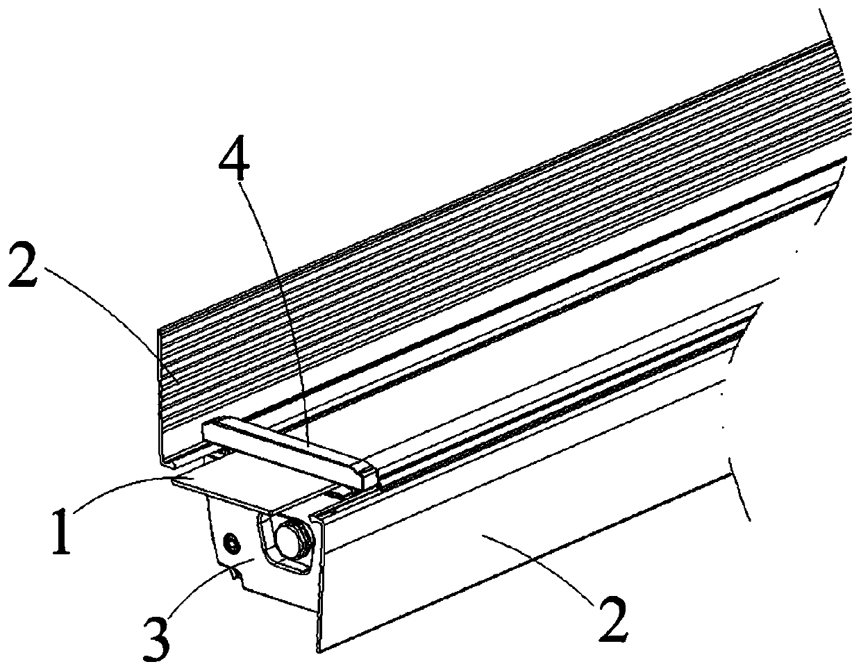
[0045] Such as Figure 1 to Figure 7 As shown, the lamp includes a lighting lamp and a lampshade that is arranged on the outside of the lighting lamp. The lampshade includes a light blocking leaf 2 and a frosted plate 1. In this embodiment, there are two light blocking leaves 2, and the orientation of the two light blocking leaves 2 is opposite and parallel. They are respectively arranged on opposite sides of the lamps. The lampshade also includes an end switch structure for clamping and fixing the frosted plate 1 and the two light shielding leaves 2 . In this embodiment, the lamp is in the shape of a strip, and both ends of the lamp are provided with end switch structures.

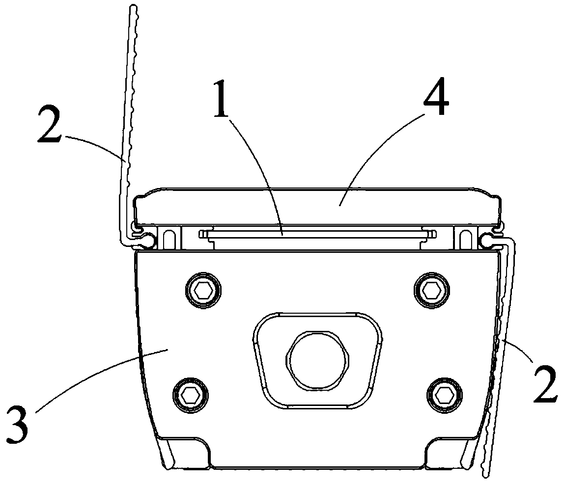
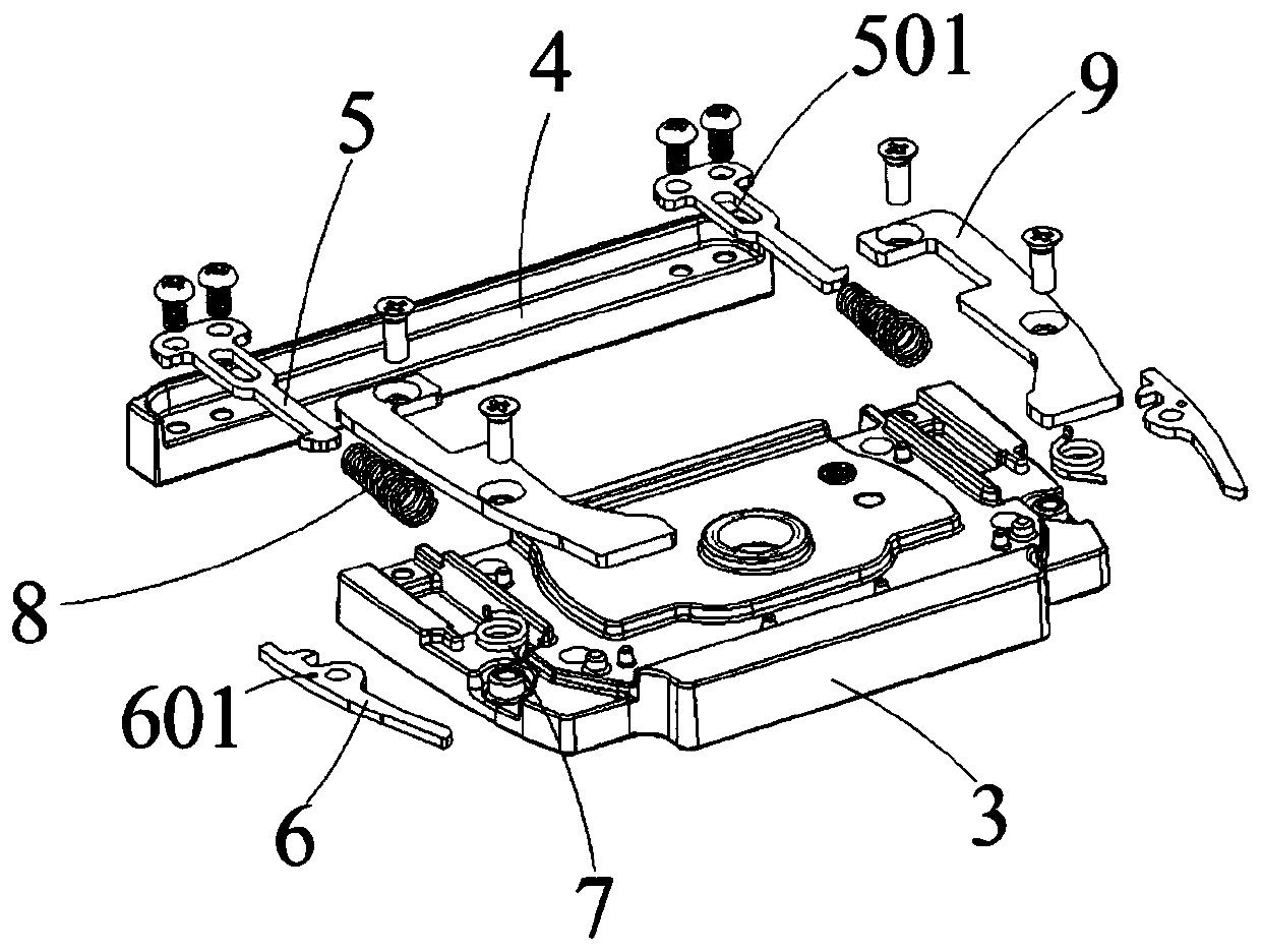
[0046] Such as figure 2 and image 3 As shown, the end switch structure includes an end cover 3 and a movable pressing plate 4. In this embodiment, the movable pressing plate 4 is guided and slidably assembled on the end cover 3 through a sliding structure. The sliding structure includes a first The s...

Embodiment 2

[0055] Embodiment 2 of the lamp of the present invention differs from Embodiment 1 in that the elastic reset member can be a spring, one end of the spring is fixed on the end cover, and the other end is fixed on the rotating member. When the rotating member is pressed, the spring will Compressed, when the force is removed, the rotating part will be pushed out under the action of the spring, thereby keeping the rotating part at the hook position.

Embodiment 3

[0056] Embodiment 3 of the lamp of the present invention differs from Embodiment 1 in that the sliding structure can be a guide rail type sliding structure, the first sliding part can be a guide rail, and the second sliding part can be a guide groove. The relative sliding with the guide groove realizes the ejection or compression of the movable pressing plate.


PUM


Abstract

The invention relates to the technical field of lamps, in particular to a lamp, a lampshade and an end switch structure. The end switch structure comprises an end cover and a movable pressing plate, the movable pressing plate is slidably installed on the end cover in a guided mode through a sliding structure, the sliding structure comprises a first sliding part arranged on the movable pressing plate and a second sliding part arranged on the end cover, the movable pressing plate opens or closes the end cover through relative sliding of the first sliding part and the second sliding part, the movable pressing plate has a closing position close to the end cover for clamping and fixing light blocking blades or a sanding plate and an opening position far away from the end cover in the sliding process, and the end cover is provided with a locking structure for fixing the movable pressing plate in the closing position, and the end cover is also provided with a pressing plate ejector for ejecting the movable pressing plate when the locking structure is opened. By adopting the end switch structure, replacement and disassembly of the light blocking blades and / or the sanding plate are facilitated.

Description

technical field [0001] The invention relates to the technical field of lamps, in particular to a lamp, a lampshade and an end switch structure. Background technique [0002] Lamps are common lighting devices. There are many styles of lamps in daily life. Most of these different styles of lamps are used in different environments. Most of the lamps are composed of lighting lamps and lampshades covering the outside of the lighting lamps. In order to meet different lighting needs, the lampshades also include light blocking leaves and frosted plates. The light blocking leaf and the frosted plate can adjust the irradiation angle and brightness of the illuminating lamp respectively. However, the light blocking leaves and the frosted plates of the lampshade in the prior art are mostly fixed by screws, which brings inconvenience to the disassembly, adjustment and cleaning of the light blocking leaves and the frosted plates. Contents of the invention [0003] The invention provide...

Claims


Application Information

Patent Timeline
Patent Type & Authority Applications(China)
IPC IPC(8): F21V17/10F21V17/16
Inventor 黄荣丰陈志曼张文炫
Owner GUANGZHOU YAJIANG PHOTOELECTRIC EQUIP CO LTD
Why Eureka
Try Eureka