Automatic rivet feeding system and method based on robot vision

A technology of robot vision and industrial robots, applied in manipulators, program-controlled manipulators, metal processing, etc., can solve the problems of low nail feeding efficiency, difficulty in taking out random rivets, and inability to convey more types.

Active Publication Date: 2019-12-03
NANJING UNIV OF AERONAUTICS & ASTRONAUTICS
View PDF9 Cites 11 Cited by
  • Summary
  • Abstract
  • Description
  • Claims
  • Application Information

AI Technical Summary

Problems solved by technology

[0005] The embodiment of the present invention provides an automatic rivet feeding system and method based on robot vision, which can solve the problems in the prior art that it is difficult to remove rivets from scattered piles, the efficiency of rivet feeding is low, and it is impossible to transport more types of rivets

Method used


Image

  • Automatic rivet feeding system and method based on robot vision
  • Automatic rivet feeding system and method based on robot vision
  • Automatic rivet feeding system and method based on robot vision

Examples


Embodiment Construction

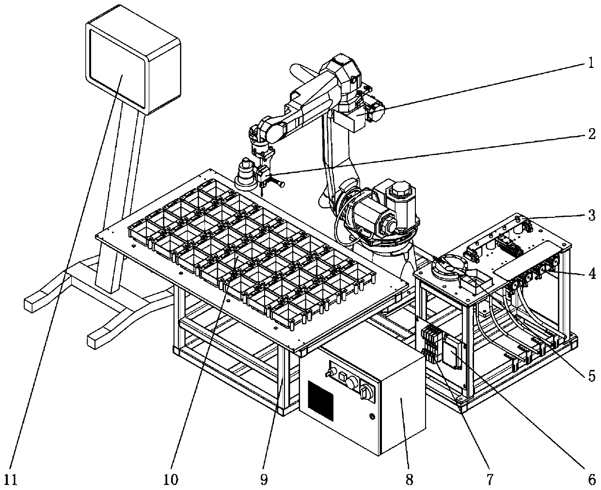
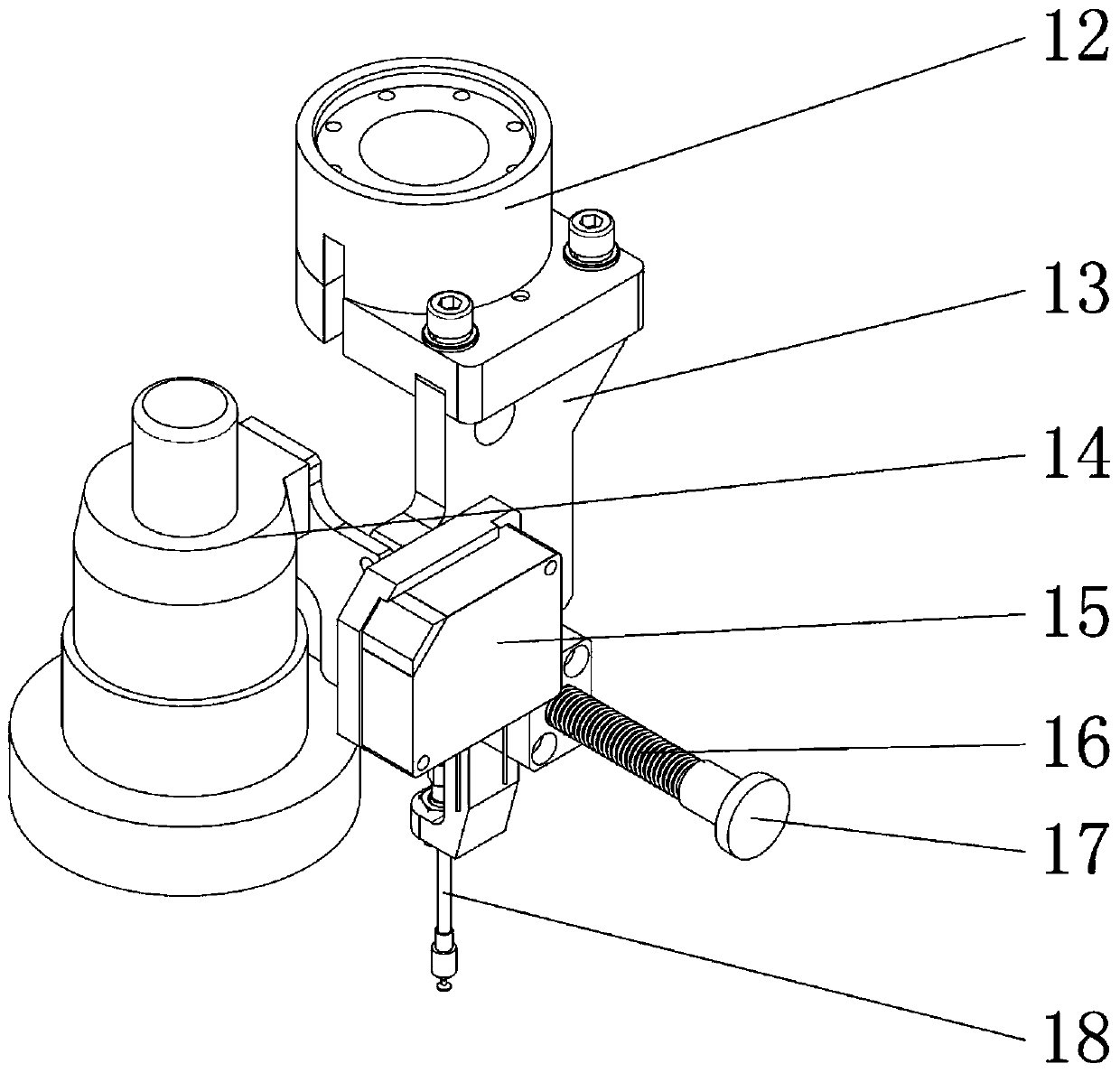
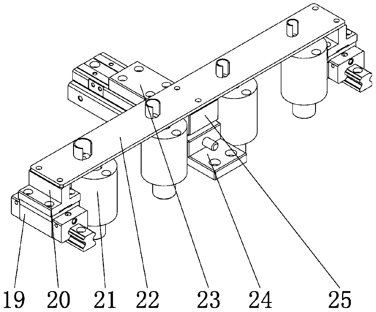
[0032] In order to enable those skilled in the art to better understand the technical solutions of the present invention, the present invention will be further described in detail below with reference to the accompanying drawings and specific embodiments. Hereinafter, the embodiments of the present invention will be described in detail. Examples of the embodiments are shown in the accompanying drawings, in which the same or similar reference numerals indicate the same or similar elements or elements with the same or similar functions. The following embodiments described with reference to the accompanying drawings are exemplary, and are only used to explain the present invention, and cannot be construed as limiting the present invention. Those skilled in the art can understand that, unless specifically stated, the singular forms "a", "an", "" and "the" used herein may also include plural forms. It should be further understood that the term "comprising" used in the specification ...


PUM


Abstract

The embodiment of the invention discloses an automatic rivet feeding system and method based on robot vision, relates to the field of intelligent manufacturing, and can solve the problems that in theprior art, rivets are difficult to take out in a scattered mode, the rivet feeding efficiency is low, and more kinds of rivets cannot be conveyed. An industrial robot, a cover plate assembly, a rivetblowing mechanism, a detection disc, a vacuum generator, a valve group and a rivet storage disc are mounted on a fixture; the multifunctional end effector is composed of a flange plate, a support, anindustrial CCD camera, a laser displacement sensor, a spring, a stirring rod and a vacuum suction nozzle. The multifunctional end effector is connected with the tail end of the industrial robot through a flange plate; the bracket is used for fixing an element on the multifunctional end effector; the industrial CCD camera is installed right in front of the support and used for obtaining rivet images. The laser displacement sensor is installed on the side face of the support and used for measuring the depth of rivets. The vacuum suction nozzle is installed below the support and used for grabbingor putting rivets. The automatic nail feeding device is suitable for automatic rivet feeding in the aircraft manufacturing process.

Description

Technical field [0001] The invention relates to the aviation manufacturing direction in the field of intelligent manufacturing, and in particular to an automatic nail feeding system and method based on robot vision. Background technique [0002] In recent years, with the help of large domestic aircraft projects such as Yun-20 and C919, the domestic aircraft manufacturing industry has been rapidly upgraded. In the design of aircraft, the comprehensive application of MBD (Model Based Definition) technology has basically got rid of the previous paper drawings and the low-efficiency design model of one institute and one institute, and the design of aircraft has reached a world-class level. However, in the manufacturing process, there are still a large number of old equipment and old processes that need to be eliminated or upgraded, and the degree of intelligence and automation needs to be further improved. With the development and development of a new generation of aerospace product...

Claims


Application Information

Patent Timeline
Patent Type & Authority Applications(China)
IPC IPC(8): B21J15/32B21J15/26B25J11/00
CPCB21J15/32B21J15/26B25J11/007B21J15/142B23P19/001B25J9/1697B25J19/023B25J15/0616B23P19/005B23P19/007B25J19/022
Inventor 田威郑义庄志炜廖文和张霖李波胡俊山
Owner NANJING UNIV OF AERONAUTICS & ASTRONAUTICS
Why Eureka
Try Eureka