
Continuous casting machine guide rail replacement flow process installation method

An installation method and streamlined technology are applied in the field of streamlined installation of replacement guide rails of continuous casting machines, which can solve the problems of difficult to guarantee installation quality and difficult to control the installation of pre-embedded panels, so as to improve work efficiency, improve traffic utilization, simplify and facilitate sexual effect

Active Publication Date: 2019-12-03
CHINA FIRST METALLURGICAL GROUP
View PDF11 Cites 1 Cited by
  • Summary
  • Abstract
  • Description
  • Claims
  • Application Information

AI Technical Summary

Problems solved by technology

[0008] In view of this, the present invention proposes a streamlined installation method for replacing guide rails in continuous casting machines, aiming to solve the problem that the accuracy of the installation position of the existing embedded board directly determines the accuracy of the guide rail position, and it is difficult to control the installation quality of the embedded board. The problem

Method used


Image

  • Continuous casting machine guide rail replacement flow process installation method
  • Continuous casting machine guide rail replacement flow process installation method
  • Continuous casting machine guide rail replacement flow process installation method

Examples


Embodiment Construction

[0023] Exemplary embodiments of the present disclosure will be described in more detail below with reference to the accompanying drawings. Although exemplary embodiments of the present disclosure are shown in the drawings, it should be understood that the present disclosure may be embodied in various forms and should not be limited by the embodiments set forth herein. Rather, these embodiments are provided for more thorough understanding of the present disclosure and to fully convey the scope of the present disclosure to those skilled in the art. It should be noted that, in the case of no conflict, the embodiments of the present invention and the features in the embodiments can be combined with each other. The present invention will be described in detail below with reference to the accompanying drawings and examples.

[0024] see Figure 1 to Figure 5 , which shows the preferred flow of the streamlined installation method for replacing the guide rail of the continuous casti...


PUM


Abstract

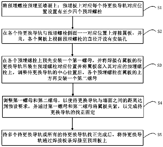
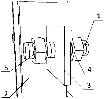
The invention provides a continuous casting machine guide rail replacement flow process installation method. The method comprises the following steps that embedded bolts are embedded into a wall surface; wing plates are welded to the side faces of the guide rails to be replaced, and mounting holes are formed in the wing plates according to the diameters of the embedded bolts; a first nut is installed on each embedded bolt in advance, the guide rail to be replaced and welded with the wing plate is hoisted to the corresponding position of the embedded bolt, the wing plate is arranged on the corresponding embedded bolt in a sleeving mode, and after the center position of the guide rail to be replaced is adjusted, a second nut is installed on the portion, above the wing plate, of each embeddedbolt; the first nut and the second nut are adjusted so that the distance between the guide rail to be replaced and the wall surface can meet the preset requirement, and the wing plate is clamped through the first nut and the second nut so that alignment and fixation of the guide rail to be replaced can be completed; and after the multiple to-be-replaced guide rails or all the to-be-replaced guiderails are aligned, the to-be-replaced guide rails are welded to the embedded plate through the welding battens.

Description

technical field [0001] The invention relates to the technical field of metallurgical equipment installation, in particular to a fluidized installation method for replacing a guide rail of a continuous casting machine. Background technique [0002] The installation of the replacement guide rail of the continuous casting machine sector has always been the focus and difficulty of the continuous casting machine construction. The quality of the installation quality of the replacement guide rail directly determines the installation quality of the continuous casting machine roll group. The overhaul of the roll set plays a vital role. [0003] At present, the guide rail installation method is usually to weld the replacement guide rail to the pre-embedded wall plate after the foundation is formed, and after the single-piece guide rail is hoisted to its design position by driving, the single-piece guide rail is welded to fix it on the The wall is pre-embedded on the board, that is to...

Claims


Application Information

Patent Timeline
Patent Type & Authority Applications(China)
IPC IPC(8): B22D11/00
CPCB22D11/00
Inventor 郑开畅耿欣周汉生尹德星黄同祥张仁强
Owner CHINA FIRST METALLURGICAL GROUP
Learn More