
A two-way hydraulic magnetic control valve capable of continuous drainage

A two-way hydraulic and magnetic control valve technology, applied in valve details, valve devices, multi-way valves, etc., can solve the problems of reduced total drainage flow, slower drainage speed, and inability to link, so as to reduce hydraulic thrust and reduce hydraulic pressure. Small resistance, the effect of avoiding clogging

Active Publication Date: 2020-11-20
嘉兴鼎尚信息科技有限公司
View PDF1 Cites 0 Cited by
  • Summary
  • Abstract
  • Description
  • Claims
  • Application Information

AI Technical Summary

Problems solved by technology

[0003] The existing waterproof drainage device needs to be maintained when the drainage channel is blocked. At this time, the drainage needs to be closed and the continuous drainage cannot be achieved. However, the patent document with the patent application number 201710861132.7 proposes "a continuous waterproof and drainage device for dual-channel water conservancy construction". It includes a waterproof and drainage valve body. A first drainage channel and a second drainage channel are opened on the waterproof and drainage valve body. The first drainage channel and the second drainage channel are vertically arranged and communicated. The first baffle plate is slidably installed in the chute, the top of the first baffle plate is fixedly installed with a fixed block, the top inner wall of the chute is provided with a first installation groove, and the top of the fixed block extends into the first installation groove, The top inner wall of the first installation groove is rotatably installed with a first support rod, the bottom end of the first support rod is rotatably installed with a first rotating shaft, and a support block is rotatably installed on the first rotating shaft, through double drainage channels, it is convenient to achieve continuous drainage purpose, and the dual channels are easy to switch back and forth, reducing the chance of clogging, but the device uses two control points of the telescopic motor and the rotary motor, and the two control points cannot be linked, which is easy to produce control errors, resulting in the total drain when switching channels. The drainage flow is reduced, which makes the drainage speed slower and affects the drainage effect

Method used


Image

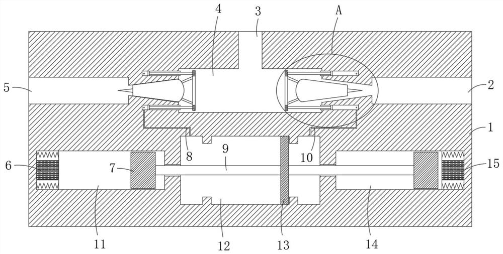
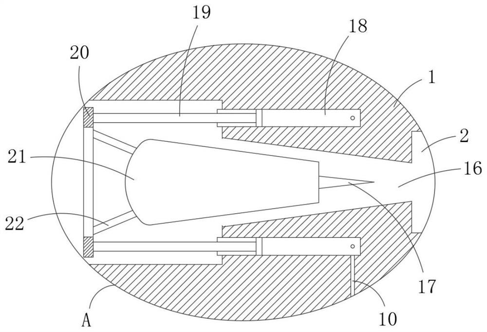
  • A two-way hydraulic magnetic control valve capable of continuous drainage
  • A two-way hydraulic magnetic control valve capable of continuous drainage

Examples


Embodiment Construction

[0024] The following will clearly and completely describe the technical solutions in the embodiments of the present invention with reference to the accompanying drawings in the embodiments of the present invention. Obviously, the described embodiments are only some, not all, embodiments of the present invention.

[0025] In describing the present invention, it should be understood that the terms "upper", "lower", "front", "rear", "left", "right", "top", "bottom", "inner", " The orientation or positional relationship indicated by "outside", etc. is based on the orientation or positional relationship shown in the drawings, and is only for the convenience of describing the present invention and simplifying the description, rather than indicating or implying that the referred device or element must have a specific orientation, so as to Specific orientation configurations and operations, therefore, are not to be construed as limitations on the invention.

[0026] refer to Figure ...


PUM


Abstract

A bidirectional hydraulic magnetic control valve capable of continuously draining water comprises a valve body, the valve body is divided into a drainage area and a control area, the drainage area comprises a water inlet, a buffer cavity, a first drainage port and a second drainage port, and the conical channels are both formed between the first drainage port and the buffer cavity and between thesecond drainage port and the buffer cavity respectively. According to the present invention, the synchronous control of the two valve mechanisms is achieved through the hydraulic magnetic control mechanism, the control errors are eliminated, and the influence of control on the drainage is reduced. The conical channels of a water impurity blocking device are solved by the conical thorns, the impactforce of the water flow on the valve mechanism is reduced through the buffer cavity, and a first electromagnetic disc and a second electromagnetic disc are buffered through the hydraulic oil in a hydraulic cavity to control a strong magnetic block to move, so that a buffer mechanism does not need to be additionally arranged. The pressure pushing is horizontal and uniform through the communicationof the multiple hydraulic cylinders of the same valve mechanism, and the bidirectional hydraulic magnetic control valve is of an integral structure and is more convenient to assemble and disassemble.

Description

technical field [0001] The invention relates to the field of hydraulic engineering, in particular to a bidirectional hydraulic magnetic control valve capable of continuous drainage. Background technique [0002] Water conservancy engineering is a project built to control and allocate natural surface water and groundwater to achieve the purpose of eliminating harm and rejuvenating profits. It is also called water engineering. Water is an indispensable and precious resource for human production and life, but its natural existence The state does not fully meet the needs of human beings. Only by building water conservancy projects can water flow be controlled, floods prevented, and water volume adjusted and distributed to meet the needs of people's life and production for water resources. Water conservancy projects require the construction of dams, dikes, Spillways, sluices, water inlets, channels, waterways, rafts, fishways and other types of hydraulic structures, in order to a...

Claims


Application Information

Patent Timeline
Patent Type & Authority Patents(China)
IPC IPC(8): F15B15/08F16K11/20F16K31/06F16K27/02F16K31/42
CPCF15B15/088F16K11/207F16K27/0254F16K27/0263F16K31/0696F16K31/42
Inventor 李礼英
Owner 嘉兴鼎尚信息科技有限公司
Learn More