Remote drainage control system of centrifugal pump

A technology for controlling systems and centrifugal pumps, applied in pump control, pumps, pump devices, etc., can solve the problems of no remote control and high labor costs

Pending Publication Date: 2021-06-25
JCHX MINING MANAGEMENT
View PDF0 Cites 0 Cited by
  • Summary
  • Abstract
  • Description
  • Claims
  • Application Information

AI Technical Summary

Problems solved by technology

Therefore, in the drainage control of the centrifugal pump, it needs to be started and stopped according to the above operations. The pump room must be

Method used


Image

  • Remote drainage control system of centrifugal pump
  • Remote drainage control system of centrifugal pump
  • Remote drainage control system of centrifugal pump

Examples


Embodiment 1

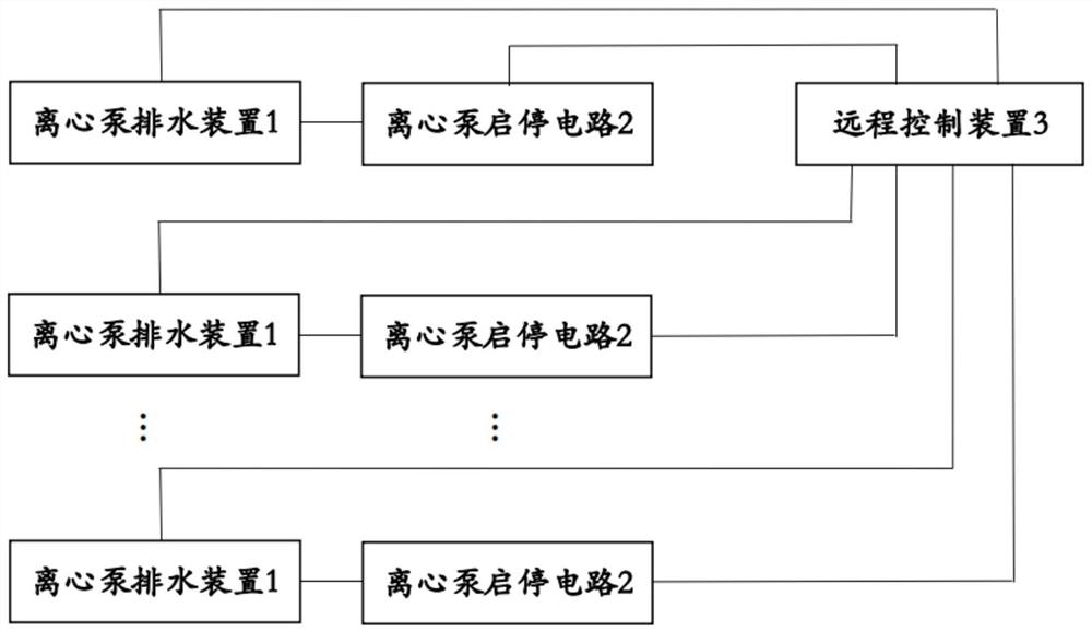
[0055] Embodiment one, as figure 1 As shown, a remote drainage control system for centrifugal pumps includes a soft starter cabinet and at least one centrifugal pump drainage device 1 arranged at the drainage field end, and at least one centrifugal pump start-stop circuit 2 is arranged inside the soft starter cabinet. The number of the centrifugal pump drainage device 1 is the same as the number of the centrifugal pump start-stop circuit 2 and corresponds one by one; it also includes a remote control device 3 arranged at the remote end;

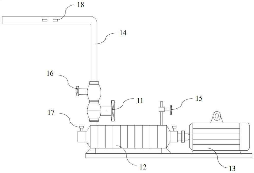
[0056] Such as figure 2 As shown, in any one of the centrifugal pump drainage devices 1, the centrifugal pump drainage device 1 includes an electric drainage valve 11, a centrifugal pump 12, a water pump motor 13 and a drainage pipeline 14; The outlet end of the pump 12 is communicated with the drain pipe 14, the electric drain valve 11 is arranged on the drain pipe 14, and the output shaft of the water pump motor 13 is connected to the cen...


PUM


Abstract

The invention relates to a remote drainage control system of a centrifugal pump. The system comprises a soft start cabinet and at least one centrifugal pump drainage device which are arranged at a drainage site end, at least one centrifugal pump start-stop circuit is arranged in the soft start cabinet, and the centrifugal pump drainage devices and the centrifugal pump start-stop circuits are the same in number and are in one-to-one correspondence; a remote control device arranged at a remote end is further included; any centrifugal pump drainage device comprises an electric drainage valve, a centrifugal pump, a water pump motor and a drainage pipeline; and the water outlet end of the centrifugal pump communicates with the drainage pipelines, the electric drainage valves are arranged on the drainage pipelines, and output shafts of the water pump motors are in transmission connection with the centrifugal pump. The water pump motors are electrically connected with the corresponding centrifugal pump start-stop circuits; and all the electric drainage valves, all the water pump motors and all the centrifugal pump start-stop circuits are electrically connected with the remote control device. Start and stop control can be conducted on drainage of the multi-stage centrifugal pump at the remote end, a water pump worker does not need to monitor operation on site, and the labor cost is low.

Description

technical field [0001] The invention relates to the technical field of well drainage, in particular to a remote drainage control system for a centrifugal pump. Background technique [0002] During the construction of prospecting shaft to level roadway, to prevent water gushing in the roadway, a temporary drainage system needs to be built. Usually, a cavern is excavated at a reasonable position in the main roadway as a temporary water tank. The water gushing from the roadway flows to the sedimentation tank in front of the water tank through the roadway ditch. Stage horizontal centrifugal pump discharges to the surface. [0003] Due to the limitation of construction site conditions, the temporary drainage system of some mines usually uses a single soft starter cabinet to control multi-stage horizontal centrifugal pumps to drain water. When the pump is started, the power required by the pump is the smallest when the flow rate is zero. Therefore, the drain gate valve should be...

Claims


Application Information

Patent Timeline
IPC IPC(8): F04D15/00F04D13/06
CPCF04D13/06F04D15/00F04D15/0088
Inventor 胡洲黄华桃朱霆李建华
Owner JCHX MINING MANAGEMENT
Why Eureka
Try Eureka