Bottom-sudden-expansion gyrating shaft well flood discharging tunnel

A technology for flood discharge tunnels and shafts, which is applied in water conservancy projects, marine engineering, coastline protection, etc., can solve problems such as limiting the discharge capacity of the swirl shaft flood discharge tunnel, heavy flood discharge load of the downstream flood discharge tunnel, and reducing the energy dissipation efficiency of the swirl shaft. , to enhance the flexibility of connection, reduce the flood discharge load, and improve the effect of energy dissipation

Active Publication Date: 2019-12-10
CHONGQING JIAOTONG UNIVERSITY +1
View PDF6 Cites 2 Cited by
  • Summary
  • Abstract
  • Description
  • Claims
  • Application Information

AI Technical Summary

Problems solved by technology

[0004] However, at the end of the vortex chamber, a constriction section with a narrow radial beam of a certain size is set to reduce the diameter of the swirl shaft to a size that meets the flood discharge requirements. Although it saves engineering costs and enhances the ability of water flow to adhere to the wall, it also leads to The energy-dissipating water body in the straight section of the lower shaft of the flow shaft is greatly reduced, thereby reducing the energy dissipation efficiency of the swirl shaft
At the same time, only a single pressure slope outlet is set in the straight section of the lower vertical shaft of the existing swirl shaft, which greatly limits the discharge capacity of the swirl shaft flood discharge tunnel
And this makes the only flood discharge tunnel at the outlet of the existing swirl shaft flood discharge tunnel bear all the flood discharge tasks of the entire shaft flood discharge system, which directly leads to a heavier flood discharge load on the downstream flood discharge tunnel

Method used


Image

  • Bottom-sudden-expansion gyrating shaft well flood discharging tunnel
  • Bottom-sudden-expansion gyrating shaft well flood discharging tunnel
  • Bottom-sudden-expansion gyrating shaft well flood discharging tunnel

Examples


Embodiment Construction

[0020] The present invention will be described in further detail below in conjunction with the accompanying drawings and specific embodiments.

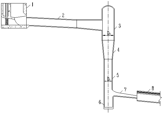
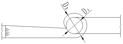
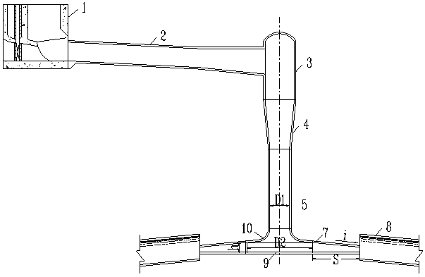
[0021] see image 3 and Figure 4 , a bottom-expanding swirl shaft flood discharge tunnel, including a lock chamber 1, an upper flat section 2, a vortex chamber 3, a contraction section 4, a vertical shaft section 5, a pressure slope section 7 and a spillway tunnel body 8. 5 vertically below is provided with a sudden expansion straight section 9, the axis of the sudden expansion straight section and the shaft straight section 5 is on the same straight line and the diameter of the sudden expansion straight section 9 is greater than the diameter of the vertical shaft straight section 5, and the sudden expansion straight section 9 passes through the connecting section 10 and The vertical shaft straight section 5 is connected and the connecting section 10 is smoothly transitioned to the vertical shaft straight section 5, the outlet of th...


PUM


Abstract

The invention discloses a bottom-sudden-expansion gyrating shaft well flood discharging tunnel. The flood discharging tunnel comprises a lock chamber, an upper flat section, a volute chamber, a contraction section, a shaft well vertical section, a slope section and a flood discharging tunnel body. A sudden-expansion vertical section is disposed on the vertical lower portion of the shaft well straight section; the axes of the sudden-expansion vertical section and the shaft well vertical section are located on the same straight line, and the diameter of the sudden-expansion vertical section is larger than that of the shaft well vertical section; the sudden-expansion vertical section is connected with the shaft well vertical section through a connecting section, and the connecting section isin smooth transition connection with the shaft well vertical section; an outlet of the shaft well vertical section is correspondingly connected with an inlet of the connecting section; an outlet of the connecting section is correspondingly connected with an inlet of the sudden-expansion vertical section; the bottom of the sudden-expansion vertical section is sealed; an outlet is formed in the sidewall of the sudden-expansion vertical section; and an inlet of the slope section is correspondingly connected with the outlet of the sudden-expansion vertical section so that the slope section communicates with the sudden-expansion vertical section. The flood discharging capacity of a gyrating shaft well is improved, the energy dissipation efficiency and effect are improved, and the flood discharging burden of an existing gyrating shaft well flood discharging tunnel is reduced.

Description

technical field [0001] The invention belongs to the technical field of flood discharge and energy dissipation of water conservancy and hydropower projects, and in particular relates to a flood discharge tunnel of a swirl shaft with sudden expansion at the bottom. Background technique [0002] With the continuous development of water conservancy construction in my country, many large-scale water conservancy projects with high dams are under construction or are being planned. Flood discharge and energy dissipation are often the key to success or failure, and corresponding energy dissipation methods are constantly emerging. Different types and types. As a relatively new form of energy dissipation, swirling shaft energy dissipation is more and more favored by water conservancy workers due to its own outstanding advantages. [0003] The front view and top view of the existing swirl shaft spillway are as follows: figure 1 and figure 2 As shown, the swirl shaft spillway consists...

Claims


Application Information

Patent Timeline
Patent Type & Authority Applications(China)
IPC IPC(8): E02B8/06
CPCE02B8/06
Inventor 袁浩彭永勤李霞刘文张绪进周世良母德伟何进朝谭家万杨树青
Owner CHONGQING JIAOTONG UNIVERSITY
Why Eureka
Try Eureka