Assistive device for lumbar puncture
An auxiliary device, lumbar puncture technology, applied in medical science, surgery, operating table, etc., can solve the problems of patients and doctors squatting on the bedside
- Summary
- Abstract
- Description
- Claims
- Application Information
AI Technical Summary
Problems solved by technology
Method used
Image
Examples
Embodiment 1
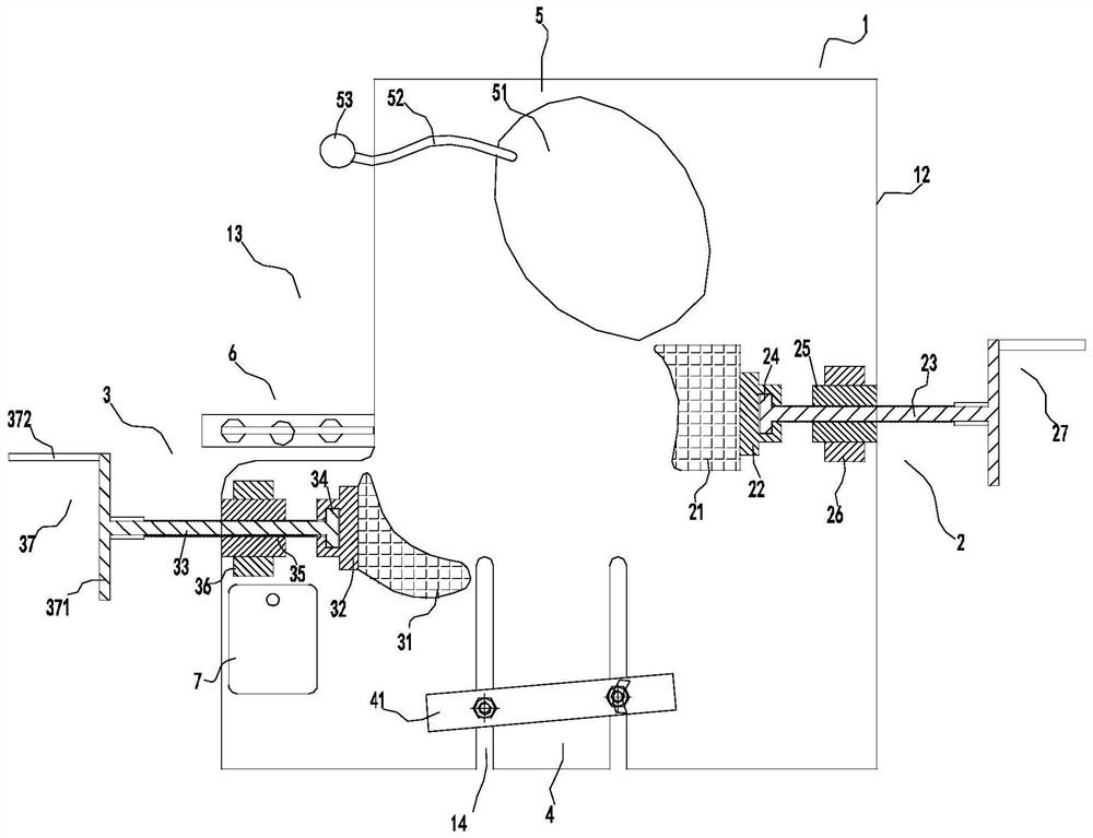
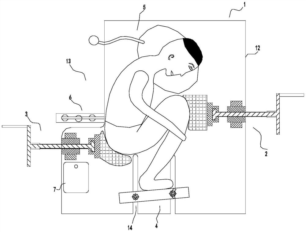
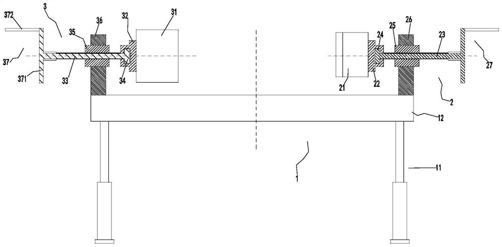
[0037] Such as Figure 1-3 As shown, a lumbar puncture auxiliary device includes a lifting bed 1, and a knee compression device 2, a hip compression device 3 and a leg compression device 4 are installed on the lifting bed 1;
[0038]The lift bed 1 includes a bed frame beam, four hydraulic lift bed legs 11 and a bed board 12, the four hydraulic lift bed legs 11 are connected with the bed frame beam, and the bed board 12 is installed on the bed On the frame beam, the left side of the bed board 12 is provided with a gap 13, and the gap 13 is a working position for medical personnel; the lower part of the bed board 12 is provided with two notches 14;
[0039] The buttocks pressing device 3 includes a buttocks fixing position 31, a buttocks connecting seat 32, a buttocks adjusting screw 33, a buttocks connecting plate 34, a buttocks screw nut 35, a buttocks fixing seat 36 and a buttocks screw driver 37, the buttocks The fixing seat 36 is installed on the left edge of the bed board...
Embodiment 2
[0047] On the basis of Embodiment 1, the driving modes of the hip lead screw driver 37 and the knee lead screw driver 27 are all improved, and both the hip lead screw driver 37 and the knee lead screw driver 27 are motor drivers.
[0048] The knee screw driver 27 is a motor driver, and the motor driver includes a driving motor 271, a reduction box 272, a shaft coupling 273, a worm screw 274, a worm wheel 275 and a casing 276, and the driving motor 271 is installed on the bottom of the bed board 12. On the right edge, the power output shaft of the driving motor 271 is connected to the reduction box 272, and the power output shaft of the reduction box 272 is connected to the worm 274 through the coupling 273, and the worm 274 is fixed to the The bearings on the two side walls of the casing 276 are rotatably installed in the casing 276, the worm wheel 275 is engaged with the worm 274, the worm wheel 275 is located directly above the worm 274 in the casing 276, and the worm wheel 2...
PUM
 Abstract
Description
Claims
Application Information
 - R&D
- Intellectual Property
- Life Sciences
- Materials
- Tech Scout
- Unparalleled Data Quality
- Higher Quality Content
- 60% Fewer Hallucinations
Browse by: Latest US Patents, China's latest patents, Technical Efficacy Thesaurus, Application Domain, Technology Topic, Popular Technical Reports.
© 2025 PatSnap. All rights reserved.Legal|Privacy policy|Modern Slavery Act Transparency Statement|Sitemap|About US| Contact US: help@patsnap.com


