A punching die

A technology of molds and mold bases, which is applied in the field of punching molds, can solve problems such as deformation of the edge of the round hole, troublesome replacement, wavy edges of the round hole, etc., and achieve the effect of reducing force deformation and improving work efficiency

Active Publication Date: 2020-09-11
来宾市精诚科技有限公司
View PDF10 Cites 0 Cited by
  • Summary
  • Abstract
  • Description
  • Claims
  • Application Information

AI Technical Summary

Problems solved by technology

[0003] 1. When punching thin steel plates, the upper mold is usually used to directly punch and blank the thin steel plates. However, due to the thinner steel plates, the edge of the punched round hole may be deformed under the action of a large impact force. As a result, the edge of the round hole is wavy, which affects the quality of the product; 2. When punching round holes with different apertures, it is necessary to replace the corresponding punching die, which is troublesome to replace, and punching dies of different specifications need to be kept and kept Regular maintenance

Method used


Image

  • A punching die
  • A punching die
  • A punching die

Examples


Embodiment Construction

[0032] Embodiments of the present invention will be described below with reference to the drawings. In the process, in order to ensure the clarity and convenience of illustration, we may exaggerate the width of the lines or the size of the constituent elements in the diagram.

[0033] In addition, the following terms are defined based on the functions in the present invention, and may be different according to the user's or operator's intention or practice. Therefore, these terms are defined based on the entire content of this specification.

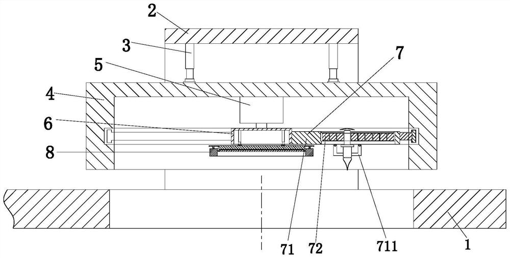
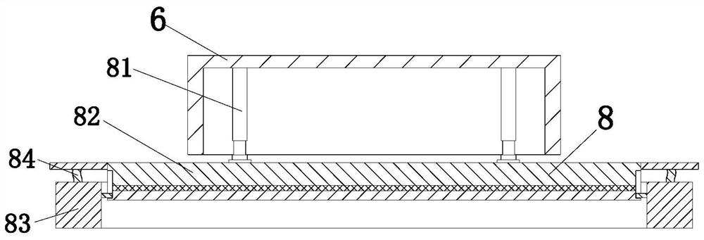
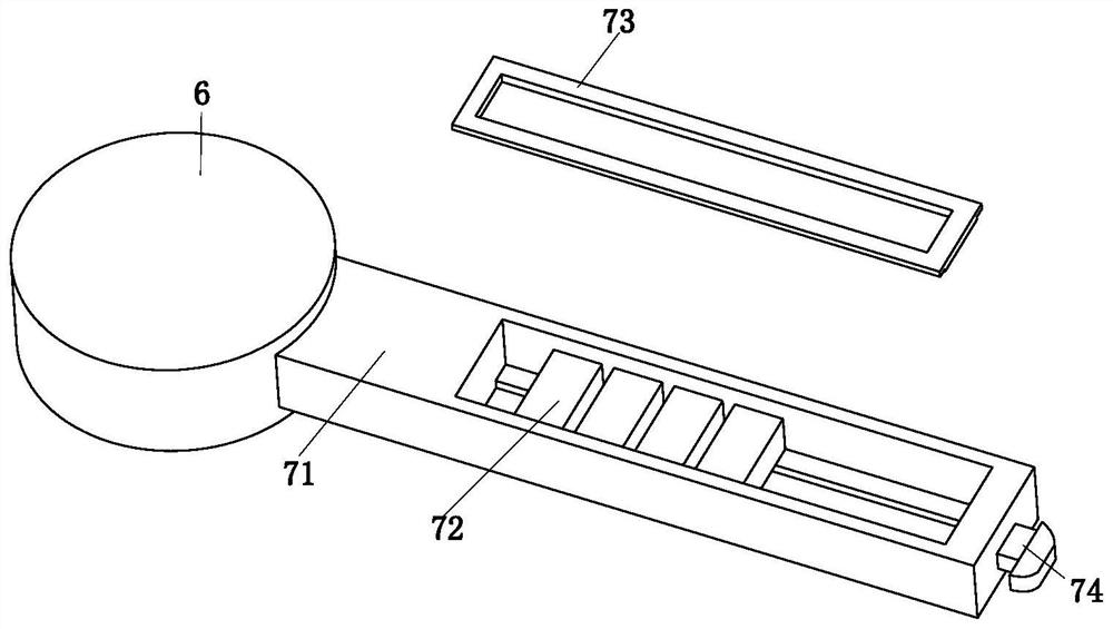
[0034] Such as Figure 1 to Figure 9 As shown, a blanking die includes a lower die 1, a mounting frame 2, a connecting cylinder 3, an upper die base 4, a motor 5, a rotating frame 6, a cutting device 7 and a punching device 8, and the lower die 1 The rear end is equipped with a mounting frame 2, the upper end of the mounting frame 2 is connected with the upper die base 4 by connecting the cylinder 3, a motor 5 is installed inside the u...


PUM


Abstract

The invention relates to a blanking die, which includes a lower die, a mounting frame, a connecting cylinder, an upper die seat, a motor, a rotating frame, a cutting device and a punching device. The rear end of the lower die is equipped with a mounting frame, and the mounting frame The upper end of the upper die base is connected with the upper die base through the connecting cylinder, a motor is installed inside the upper die base, a rotating frame is installed on the output shaft of the motor, a cutting device is installed at the right end of the rotating frame, and a punching device is installed at the lower end of the rotating frame. The invention can solve the problem that when punching a thin steel plate, the upper die is usually used to directly punch and blank the thin steel plate, but because the thickness of the thin steel plate is relatively thin, the edge of the punched round hole may be under the action of a relatively large impact force. Deformation occurs, resulting in wavy edges of round holes. When punching round holes with different apertures, it is necessary to replace the corresponding punching dies. The replacement is more troublesome, and punching dies of different specifications require standing and regular maintenance.

Description

technical field [0001] The invention relates to the field of punching dies, in particular to a punching die. Background technique [0002] Blanking die is an indispensable process equipment in stamping production. It is mainly used for blanking and punching of various plates. The working part of the die is the cutting edge of the convex and concave dies. The main task of the punching die is to separate the materials. , when punching a thin steel plate, the upper die is usually used to punch and cut the thin steel plate. However, due to the thinner thickness of the thin steel plate, some situations may be encountered during punching: [0003] 1. When punching thin steel plates, the upper mold is usually used to directly punch and blank the thin steel plates. However, due to the thinner steel plates, the edge of the punched round hole may be deformed under the action of a large impact force. As a result, the edge of the round hole is wavy, which affects the quality of the pro...

Claims


Application Information

Patent Timeline
Patent Type & Authority Patents(China)
IPC IPC(8): B21D37/10B21D28/14B21D28/34
CPCB21D37/10B21D28/14B21D28/34
Inventor 黄丹丹江恰
Owner 来宾市精诚科技有限公司
Why Eureka
Try Eureka