LED light mixing system

A light mixing and beam technology, applied in the field of light mixing, can solve the problem of uneven light mixing of LED light sources, and achieve the effects of uniform light mixing, uniform color mixing and cost saving.

Pending Publication Date: 2019-12-13
PHILIPS LIGHTING CHINA INVESTMENT CO LTD
View PDF0 Cites 0 Cited by
  • Summary
  • Abstract
  • Description
  • Claims
  • Application Information

AI Technical Summary

Problems solved by technology

[0003] The present invention aims at overcoming at least one defect of the above-mentioned prior art, and provides an LED light mixing system with uniform color mixing and light mixing, which is used to solve the problem of uneven light mixing of LED light sources

Method used


Image

  • LED light mixing system
  • LED light mixing system
  • LED light mixing system

Examples


Embodiment 1

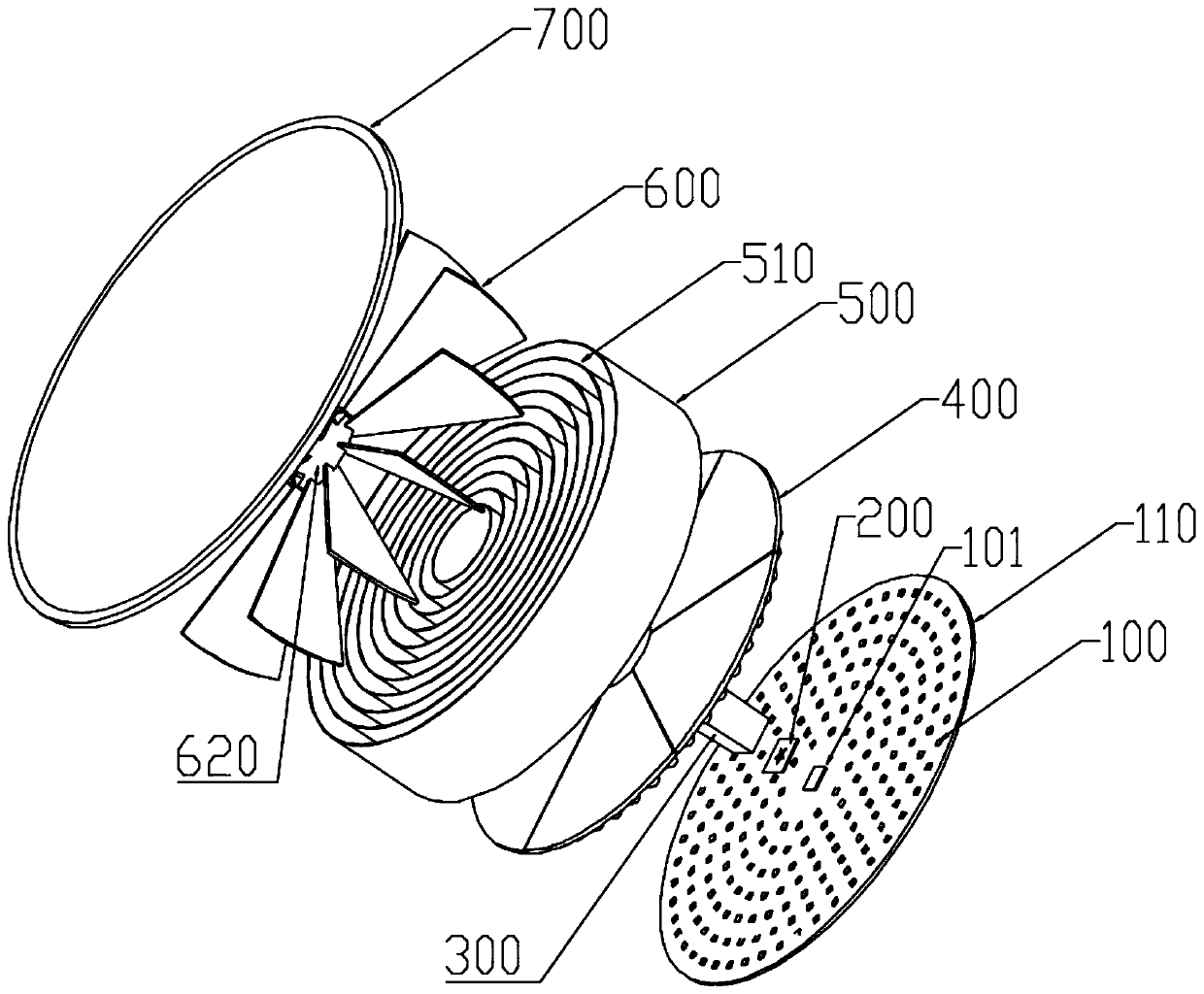
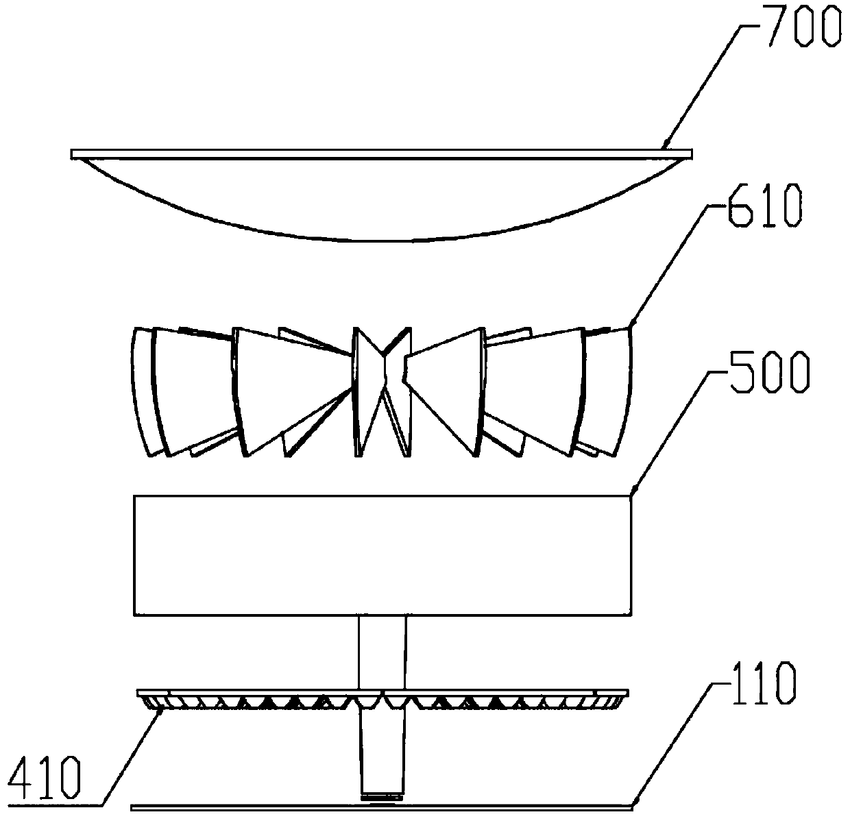
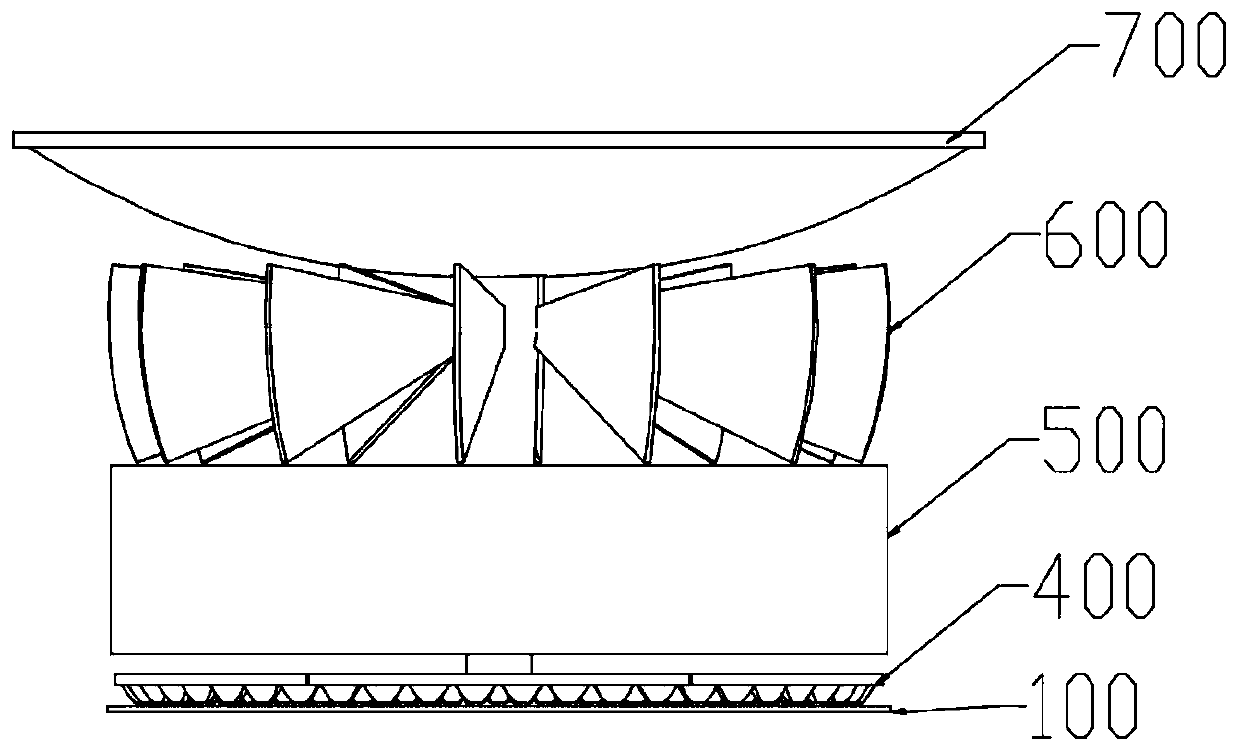
[0032] Such as figure 1 with figure 2 As shown, an LED light mixing system includes a number of LED100 arranged in a certain pattern or shape and a PCB board 110 for installing the LED100. A light mixing module 500 is provided in the light emitting direction of the LED100. The light mixing module The shape of the cross-section of 500 matches the shape formed by the arrangement of LED100, and the light mixing module 500 is provided with a gap for the light emitted by the LED100 to pass through, and the light emitted by the LED100 is at least partially passed through the light mixing module 500. The sidewall of the gap formed by the module 500 reflects and mixes the light and emits it.

[0033] In this technical solution, the light mixing module 500 is arranged in the light output direction of the LED100. When the light beam emitted by the LED100 passes through the light mixing module 500, a small part of the light beam directly passes through the gap of the light mixing modul...

Embodiment 2

[0066] The difference between this embodiment and Embodiment 1 is that the fixing bar 800 is a comb-shaped fixing member, and the cylinders 510 are connected and fixed by a comb-shaped fixing member, and the comb teeth of the comb-shaped fixing member extend into inside the cylinder 510 .

[0067]The comb-shaped fixing member fixes the light mixing assembly into the light mixing module 500, which is convenient for installation. The comb teeth spacing of the comb-shaped fixing member is slightly smaller than or equal to the thickness of the side wall of the cylinder, so that the comb-shaped structure clamps the light mixing assembly, thereby making the light mixing module 500 more stable. Moreover, the comb-shaped fixing member is located between the installation distances of two adjacent LEDs 100 , so that the light path emitted by the LEDs 100 is not blocked.

[0068] Preferably, the pair of comb-shaped fixing members is located between the installation positions of two adja...


PUM


Abstract

The invention discloses an LED light mixing system. The LED light mixing system includes a plurality of LEDs arranged in a certain pattern or shape and a PCB board for mounting the LEDs; a light mixing module is arranged in the light output direction of the LED; the shape of the cross section of the light mixing module matches the shape formed by the LED arrangement; the light mixing module is provided with a gap through which the light emitted by the LEDs passes; and at least part of the light emitted by the LEDs is mixed and reflected by the light mixing module and then emitted. According tothe technical scheme, the light mixing module is arranged in the light emitting direction of the LEDs, so that at least part of the light emitted by the LEDs is light-mixed and color-mixed by the light mixing module and then emitted, so as to achieve the beneficial effect of uniform color mixing and light mixing; and compared with the traditional light mixing technology, the LED light mixing system has the beneficial effects of uniform color mixing, simple, effective and cost saving.

Description

technical field [0001] The present invention relates to the technical field of light mixing, and more specifically, to an LED light mixing system. Background technique [0002] In the prior art, in order to obtain a high-power lighting system, a plurality of LEDs are generally arranged together according to a certain quantity ratio, and the brightness thereof is sufficient to replace a traditional platinum light bulb. But because it emits light through multiple LEDs, it is easy to cause local light spots to be too bright. In view of this situation, most conventional technologies use light guides or integrators to mix light. However, the light source mixed by the light guide or the integrator will produce an included angle due to the relationship between the beam angle, forming a so-called dark band area. On the other hand, in order to obtain better color mixing and light mixing effects, it is necessary to carry out highly precise process improvement on the structure of the...

Claims


Application Information

Patent Timeline
IPC IPC(8): F21K9/20F21K9/69F21K9/62F21Y115/10
CPCF21K9/20F21K9/69F21K9/62F21Y2115/10
Inventor 蒋伟楷其他发明人请求不公开姓名
Owner PHILIPS LIGHTING CHINA INVESTMENT CO LTD
Why Eureka
Try Eureka