Combustion chamber heat protection wall structure using fuel self-suction sweat cooling

A sweat cooling and thermal protection technology, applied in combustion chambers, continuous combustion chambers, combustion methods, etc., can solve problems such as insufficient fuel heat sink, easy coking and clogging, and achieve the effects of lowering temperature, avoiding coking and clogging, and realizing recycling

Active Publication Date: 2020-07-28
TSINGHUA UNIV
View PDF9 Cites 0 Cited by
  • Summary
  • Abstract
  • Description
  • Claims
  • Application Information

AI Technical Summary

Problems solved by technology

The traditional cooling method uses fuel regenerative cooling to protect the wall of the combustion chamber from heat. However, as the speed of the aircraft further increases and the combustion temperature continues to increase, the problems of insufficient fuel heat sink and easy coking and blockage in the above-mentioned traditional cooling method are becoming more and more prominent. , so it is necessary to adopt a more efficient and stable thermal protection method to cool the combustion chamber wall of the hypersonic engine to adapt to the rapid development of aircraft technology

Method used


Image

  • Combustion chamber heat protection wall structure using fuel self-suction sweat cooling
  • Combustion chamber heat protection wall structure using fuel self-suction sweat cooling
  • Combustion chamber heat protection wall structure using fuel self-suction sweat cooling

Examples


Embodiment 1

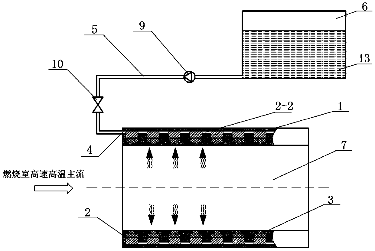
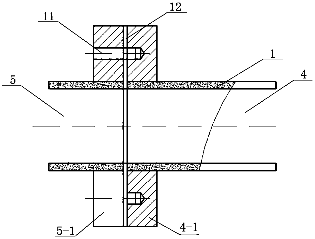
[0030] Such as Figure 2-6 As shown, this embodiment provides a combustion chamber heat protection wall structure that utilizes self-suction and sweating of fuel oil for cooling. The combustion chamber wall is set as a heat protection wall structure. Layer 1, foam layer 2 and porous layer 3, one side of foam layer 2 is provided with fuel inlet 4, and fuel inlet 4 is connected with external fuel tank 6 through fuel pipeline 5; 6 enters the foam layer 2 through the fuel pipeline 5, and under the capillary force of the two porous structures of the foam layer 2 and the porous layer 3, the fuel oil 13 is in the porous layer 3 and the inner wall of the combustion chamber, that is, the inner surface of the porous layer 3 Perform strong convective heat exchange and vaporization, absorb a large amount of heat, and can effectively reduce the temperature of the combustion chamber wall. The fuel vapor formed by vaporization during heat exchange forms a thin film boundary layer on the inne...


PUM


Abstract

The prevent invention discloses a combustion chamber thermal protection wall structure utilizing fuel automatic suction transpiration cooling. The combustion chamber thermal protection wall structurecomprises a high-temperature resistant outer wall layer, a foam layer and a porous layer which are sequentially arranged from outside to inside, wherein one side of the foam layer is provided with a fuel inlet that is connected to an external oil tank through a fuel pipeline. According to the invention, capillary force of the fuel in a porous structure is used as the driving force to realize fuelautomatic suction transpiration cooling; liquid fuel is used as a coolant, and the boiling point of the fuel is higher than that of water and lower than a coking temperature, thus avoiding coking blockage in the porous layer; the fuel performs convection heat exchange and is vaporized in the porous layer, thus a large amount of heat is absorbed, and the temperature of the wall of a combustion chamber is reduced; and the fuel after heat exchange can penetrate into the interior of the combustion chamber from the porous layer to participate in combustion and provide power, and after phase changevaporization, fuel oil vapor can form a film boundary layer on the inner surface of the thermal protection wall structure to block the heat transfer from a high-speed and high-temperature mainstream to the wall of the combustion chamber, so that the cooling effect is efficient and stable, and the applicability is high.

Description

technical field [0001] The invention relates to the field of thermal protection of the engine combustion chamber wall, in particular to a thermal protection wall structure of the combustion chamber which is cooled by self-absorption and sweating of fuel. Background technique [0002] Aerospace technology represents the country's cutting-edge science and technology level, and is also a symbol of a country's comprehensive national strength. It is of great significance to the country's military, economic, transportation and other fields, and has received great investment from all countries in the world. In recent years, in order to meet higher and faster flight requirements, hypersonic (Ma>5, Ma is the Mach number) aircraft has been developed rapidly, and the resulting increase in aerodynamic heating and engine combustion chamber temperature has made thermal protection become a key problem. Such as figure 1 As shown, the scramjet engine is commonly used in hypersonic aircr...

Claims


Application Information

Patent Timeline
Patent Type & Authority Patents(China)
IPC IPC(8): F23R3/42
CPCF23R3/42
Inventor 姜培学胥蕊娜李晓阳
Owner TSINGHUA UNIV
Why Eureka
Try Eureka