
Inverter optimal output control method and device
A technology of output control and inverter, applied in the field of photovoltaic power generation, can solve the problem that the power quality cannot be optimal, and achieve the effect of optimal output performance
- Summary
- Abstract
- Description
- Claims
- Application Information
AI Technical Summary
Problems solved by technology
Method used
Image

Examples
Embodiment 1
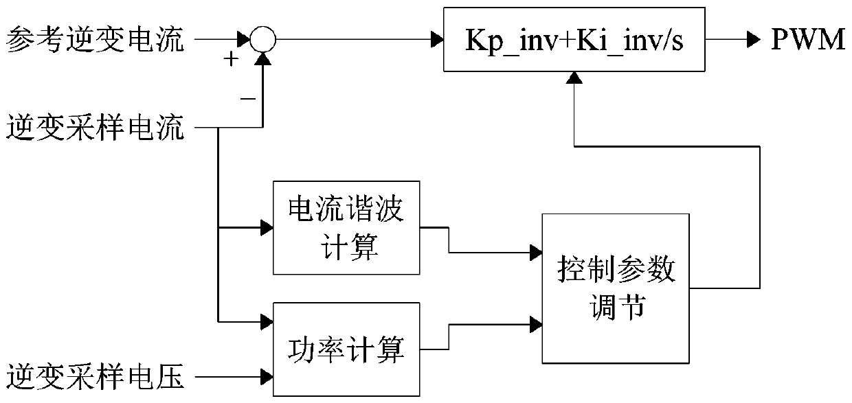
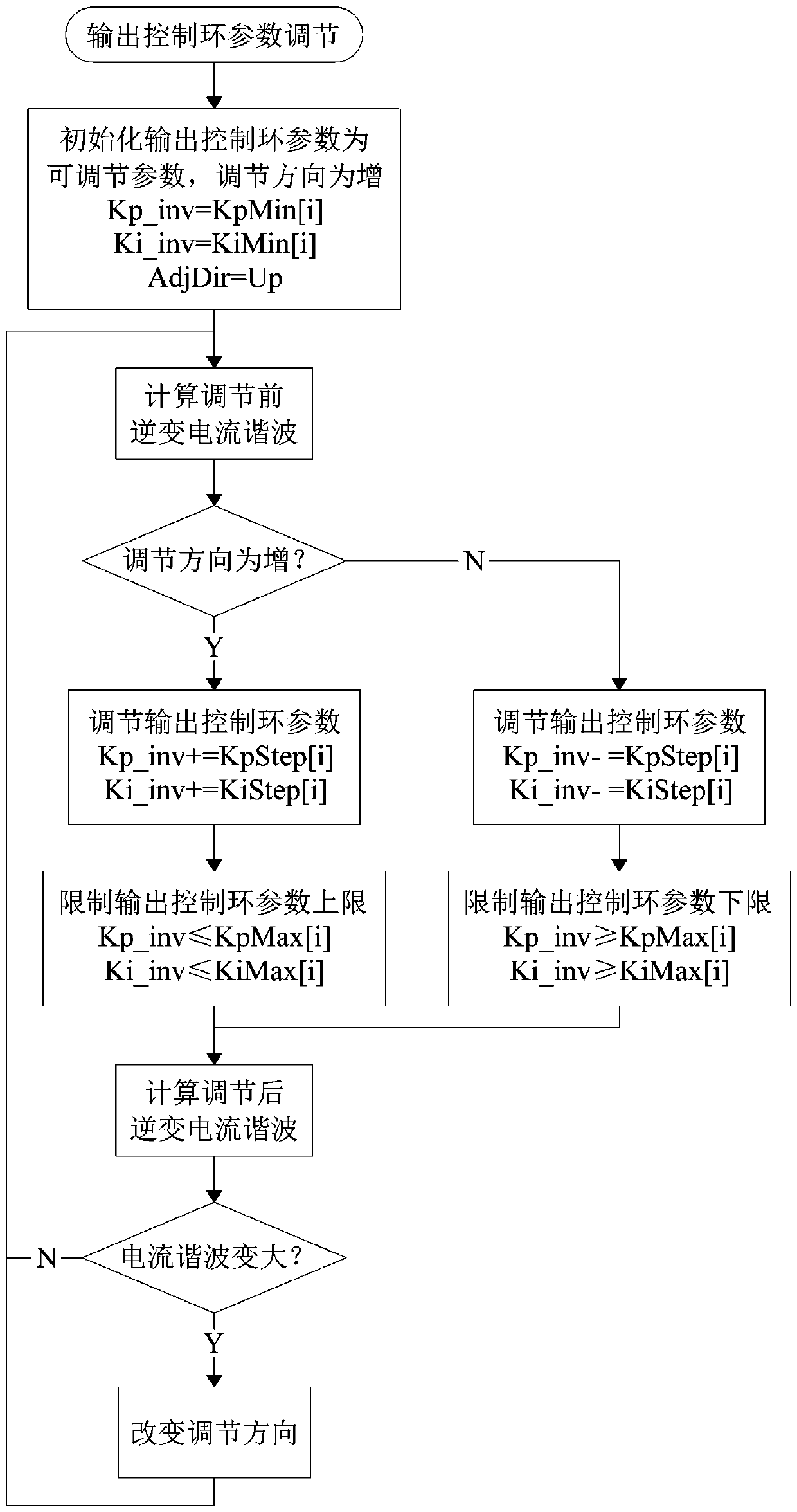
[0022] Embodiment 1: An inverter optimal output control method for controlling the output of the inverter by adjusting the parameters of the output control loop, including a preparation stage and an implementation stage.
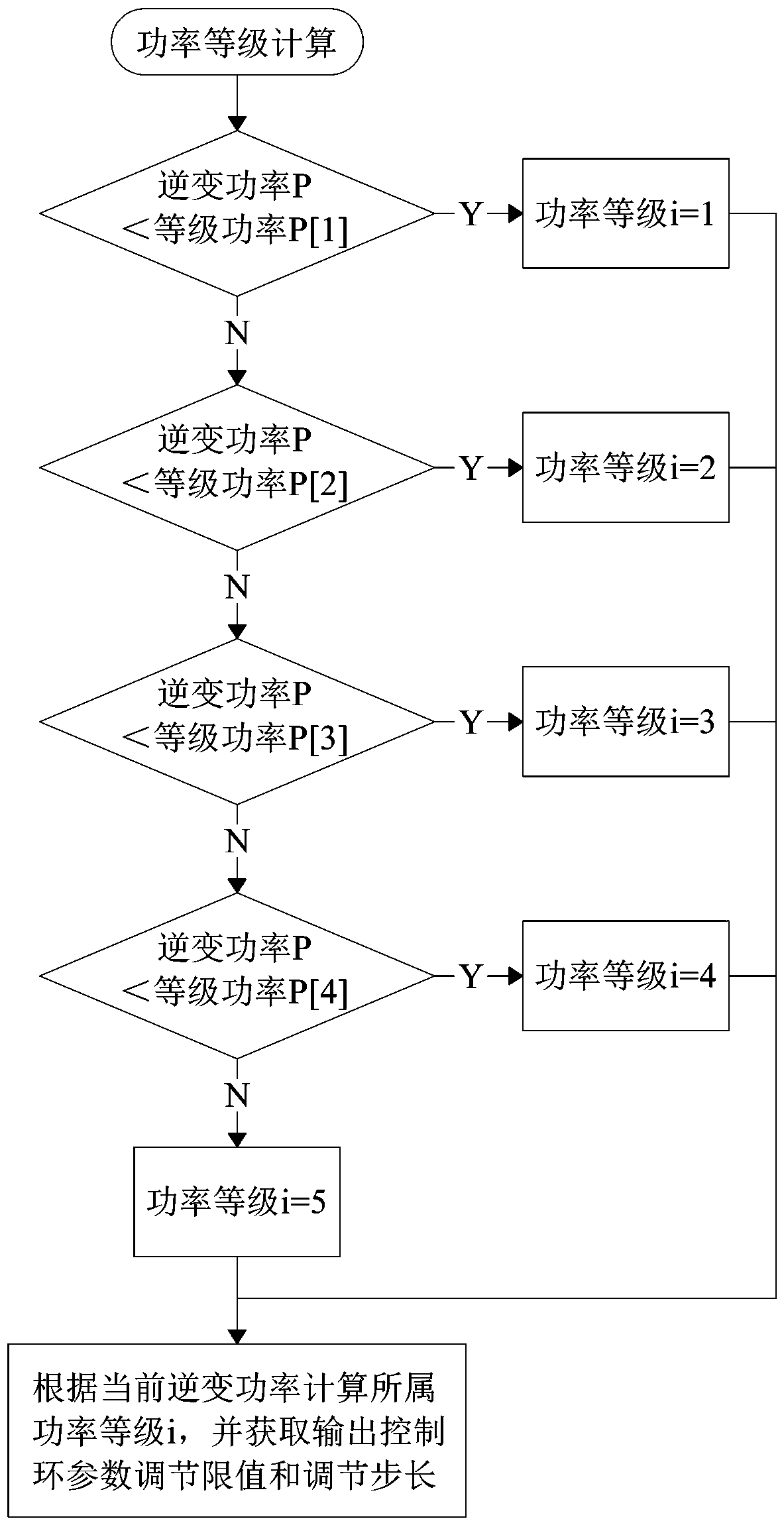
[0023] In the preparation stage, the inverter power of the inverter is divided into multiple power levels according to the power node value P[k] in advance, and the output control loop parameter adjustment limit and adjustment step size corresponding to each power level are preset. The power node value P[k] is used to divide power levels, so it can also be called level power P[k]. In this embodiment, four power node values P[k] are set, namely P[1], P[2], P[3], P[4], and P[1]<P[2]< P[3]<P[4], the inverter power is divided into 5 power levels. If the inverter power P<P[1] of the inverter belongs to the first power level, if P[1]≤inverter power of the inverter P<P[2] then it belongs to the second power level, if If P[2]≤the inverter power of the inverter P...
PUM
 Abstract
Description
Claims
Application Information