
Longitudinal-bending coupling double-foot linear plate type piezoelectric motor

A piezoelectric motor and coupling technology, applied in piezoelectric effect/electrostrictive or magnetostrictive motors, generators/motors, electrical components, etc., can solve the problems of coupled vibration, difficult assembly, large size, etc. Good output performance, easy miniaturization, high energy density effect

Pending Publication Date: 2022-05-06
SHANGHAI UNIV OF ENG SCI
View PDF2 Cites 0 Cited by
  • Summary
  • Abstract
  • Description
  • Claims
  • Application Information

AI Technical Summary

Problems solved by technology

[0003] Due to the limitation of the structure and working principle of the linear motor, the current linear motor still has problems such as complex structure, large volume, insufficient output performance and difficult assembly.
The invention patent with the Chinese patent application number 201610009537.3 discloses a linear ultrasonic motor with laminated piezoelectric ceramics. The linear motor is driven by a single foot, which will lead to insufficient output performance of the motor and low energy density of the motor.
The invention patent with the Chinese patent application number 201810064276.4 discloses a miniature horizontal-plate type longitudinal-bend coupling linear ultrasonic motor. Vibration may cause coupling vibration of the preload device and damage the stability of the motor structure

Method used


Image

  • Longitudinal-bending coupling double-foot linear plate type piezoelectric motor
  • Longitudinal-bending coupling double-foot linear plate type piezoelectric motor
  • Longitudinal-bending coupling double-foot linear plate type piezoelectric motor

Examples


Embodiment Construction

[0029] The following will clearly and completely describe the technical solutions in the embodiments of the present invention with reference to the drawings in the embodiments of the present invention. Obviously, the described embodiments are part of the embodiments of the present invention, not all of them. Based on the embodiments of the present invention, all other embodiments obtained by persons of ordinary skill in the art without making creative efforts shall fall within the protection scope of the present invention.

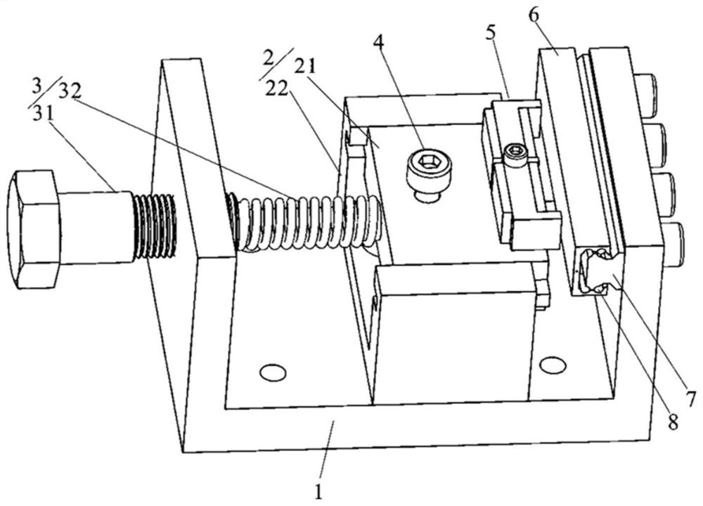
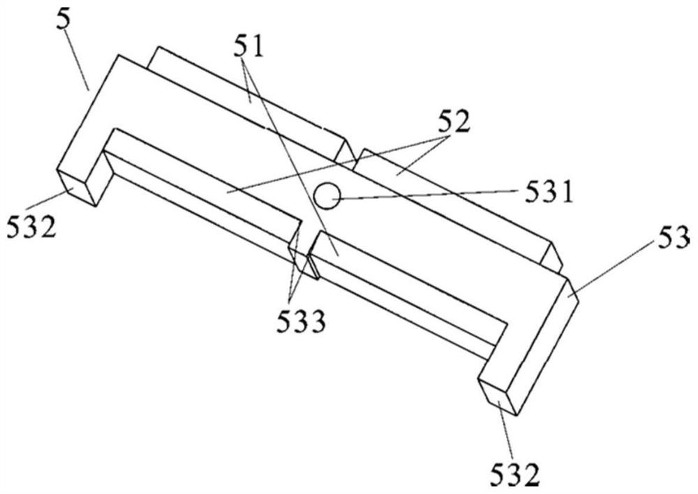
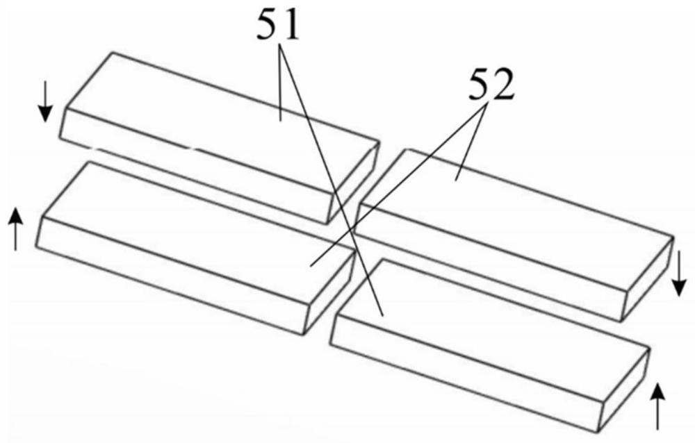
[0030] The following is attached Figure 1-6 The embodiment of the present invention is described in detail. A longitudinal bending coupled biped linear plate piezoelectric motor provided in this embodiment includes a stator 5, a mover slider 7, a base 1, a pre-pressure device 3, and a sliding mechanism 2. A guide rail 7 is fixed on the baffle on the right side of the base, and a ball 8 is arranged between the mover slider 6 and the guide rail 7 to reduce ...


PUM


Abstract

The invention relates to a longitudinal bending coupling double-foot linear plate type piezoelectric motor, which comprises a stator, a mover sliding block and an assembly base body, the assembly base body comprises a base, a sliding mechanism and a pre-tightening force device, the base is provided with a guide rail for the mover sliding block to move, the stator comprises a first piezoelectric plate, a second piezoelectric plate and an elastic body, and the elastic body is arranged on the first piezoelectric plate. The first piezoelectric plate and the second piezoelectric plate are arranged on the elastic body and are fixed on the sliding mechanism, and the sliding mechanism is connected with the pre-tightening force device; the pretightening force device pushes the driving foot of the elastic body to make contact with the rotor sliding block through the sliding mechanism, and the stator generates elliptical track movement at the end of the driving foot through a longitudinal bending coupling mode, so that the rotor sliding block is driven to do linear movement through the friction effect. The bidirectional movement of the motor can be realized by switching the driving electrodes. Compared with the prior art, the motor has the advantages of being capable of keeping high output performance, simple to assemble, small in two-phase modal frequency difference, beneficial to stable output of the motor and the like.

Description

technical field [0001] The invention relates to the technical field of piezoelectric motors, in particular to a longitudinal bending coupled biped linear plate piezoelectric motor. Background technique [0002] The linear piezoelectric motor uses the inverse piezoelectric effect of piezoelectric ceramics to make the elastic body vibrate at a high frequency and slightly, and then converts electrical energy into mechanical energy through the frictional coupling between the stator and the mover to drive the mover to output linear motion. Linear motors have the characteristics of simple structure, direct drive of loads, high positioning accuracy and no electromagnetic interference. It has broad application prospects in micro-machines, precise positioning, and low-power drives. [0003] Due to the limitation of the structure and working principle of the linear motor, the current linear motor still has problems such as complex structure, large volume, insufficient output performa...

Claims


Application Information

Patent Timeline
Patent Type & Authority Applications(China)
IPC IPC(8): H02N2/02H02N2/04H02N2/06
CPCH02N2/02H02N2/04H02N2/06
Inventor 范平清付道阔袁涛
Owner SHANGHAI UNIV OF ENG SCI
Learn More