Display panel and preparation method thereof and display device

A technology for display panels and array substrates, applied in nonlinear optics, instruments, optics, etc., can solve problems such as frame limitation and thickness increase, and achieve the effect of reducing frame width, reducing the risk of wire breakage, and being easy to implement

Inactive Publication Date: 2019-12-17
WUHAN CHINA STAR OPTOELECTRONICS TECH CO LTD
View PDF14 Cites 23 Cited by
  • Summary
  • Abstract
  • Description
  • Claims
  • Application Information

AI Technical Summary

Problems solved by technology

[0005] The present invention provides a display panel, its preparation method, and a display device. By arranging a conductive film at the end of the array substrate or color filter substrate away from the display area, the chip-on-chip film is boun

Method used


Image

  • Display panel and preparation method thereof and display device
  • Display panel and preparation method thereof and display device
  • Display panel and preparation method thereof and display device

Examples


Embodiment 1

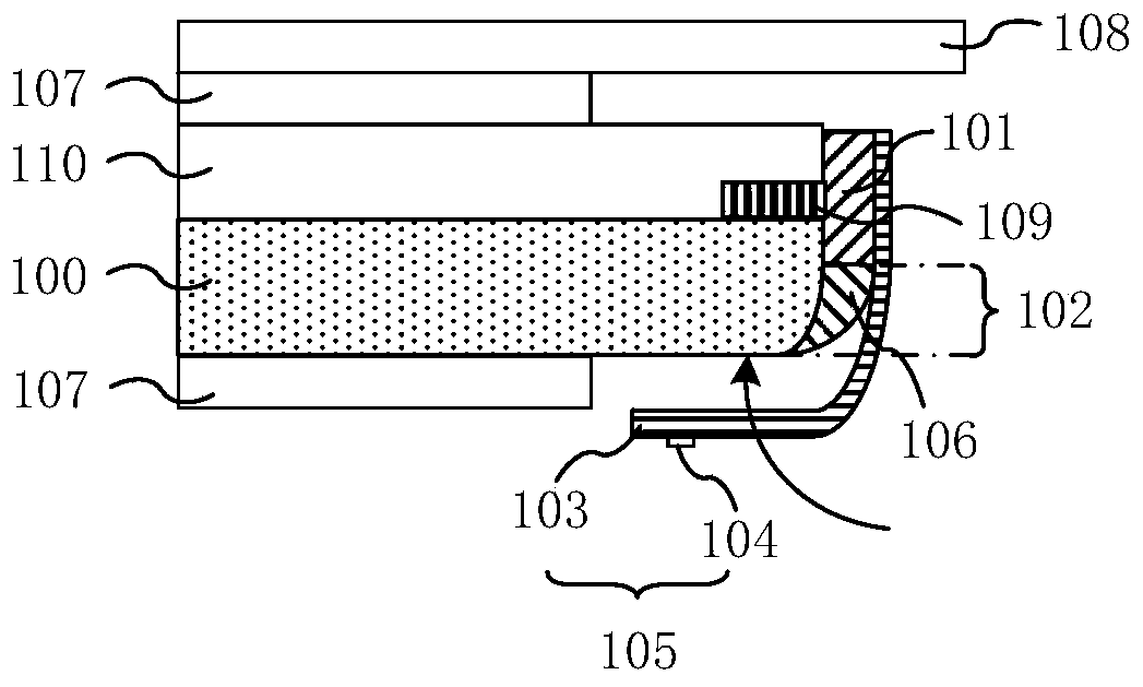
[0038] like Figure 1A Shown is a schematic structural view of the display panel of the present invention; the display panel includes an array substrate 100, and a color filter substrate 110 opposite to the array substrate 100; The upper and lower polarizers 107 at the bottom; the package cover 108 . In addition, the display panel also includes liquid crystal molecules disposed between the color filter substrate 110 and the array substrate 100 , a back film disposed at the bottom of the panel and other parts not shown.

[0039] like Figure 1A The schematic structural diagram of the display panel shown is mainly the non-display area of ​​the display panel, and the display area of ​​the display panel is not shown in the drawing. refer to Figure 1A It can be seen that the side of the array substrate 100 is flush with the side of the color filter substrate 110 to form a side binding area, and the side binding area is located between the array substrate 100 and the color filter s...

Embodiment 2

[0055] like image 3 Shown is a schematic diagram of another display panel structure, and the marks in the figure are the same as Figure 1A The marks in are the same and will not be repeated here. Depend on image 3 It can be known that the array substrate 100 is flush with the cutting line of the color filter substrate 110 to form a side binding area, the conductive film 101 is arranged in the side binding area, and the chamfer 102 is arranged in the color filter substrate 110. On the side of the film substrate 110 , the COF film 105 is bent along the chamfer 102 and bound to the side of the color filter substrate 110 away from the array substrate 100 .


PUM

PropertyMeasurementUnit
Surface roughnessaaaaaaaaaa

Abstract

The invention provides a display panel and a preparation method thereof and a display device. Conductive films are arranged at the end parts of an array substrate and a color film substrate of which the sides are flush with each other. A lead angle is formed at the edge, corresponding to the color film substrate or the array substrate, of a binding area. A chip on film is attached to the conductive film, and the chip on film is bent along the lead angle to realize binding. Therefore, the border width of the display panel is reduced, and the risk of line breakage easily occurring in the borderarea of the display panel is reduced.

Description

technical field [0001] The invention relates to the field of display technology, in particular to a display panel, a manufacturing method thereof, and a display device. Background technique [0002] The progress of display technology promotes the diversified development of display devices, and full-screen display devices and flexible display devices are becoming the mainstream of display device development. In order to increase the screen-to-body ratio of the display panel, COG technology or COF technology is generally used to bind the driver chip on the array substrate or flexible circuit board, so as to reduce the lower frame area of ​​the display panel and increase the screen-to-body ratio of the display panel. [0003] However, COG technology and COF technology also have their own shortcomings. For example, COG technology needs to reserve a space on the array substrate for binding the driver chip and the flexible circuit board, so there is still a certain limit on the si...

Claims


Application Information

Patent Timeline
IPC IPC(8): G02F1/1345G02F1/1339G02F1/1335
CPCG02F1/133514G02F1/1339G02F1/13452G02F1/13456
Inventor 郑颖博
Owner WUHAN CHINA STAR OPTOELECTRONICS TECH CO LTD
Why Eureka
Try Eureka