Indoor horizontal bar

A technology of rollers and vertical rods, which is applied to horizontal bars, sports accessories, gymnastics equipment, etc., can solve the problems of unsafety and large space occupation, and achieve the effect of safe and convenient use and saving installation space

Inactive Publication Date: 2019-12-20
许刘彬
View PDF11 Cites 0 Cited by
  • Summary
  • Abstract
  • Description
  • Claims
  • Application Information

AI Technical Summary

Problems solved by technology

[0006] In order to overcome the shortcoming that the single rod installation takes up a large space indoors and is unsafe, the technical problem i

Method used


Image

  • Indoor horizontal bar

Examples


Example Embodiment

[0013] Example 1

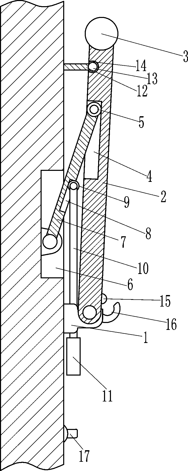
[0014] A horizontal bar for indoor use, see figure 1 , Including the mounting block 1, the vertical rod 2, the cross rod 3, the first roller 5, the swing rod 7, the second roller 9, the connecting rod 10, the handle 11, the mounting rod 12 and the plastic ball 13. Mounting block 1 is provided on each side, and the mounting block 1 is connected to the wall by bolts. Both the front and rear mounting blocks 1 are rotatably provided with vertical rods 2, and the tops of the vertical rods 2 on the front and rear sides are connected with cross rods. 3. The vertical rod 2 is connected to the cross rod 3 by welding. The upper part of the vertical rod 2 is provided with a first slide groove 4, and the first slide groove 4 is provided with a first roller 5 in a sliding manner. The right side of the wall There are first grooves 6 on the front and rear sides. The first groove 6 is located above the mounting block 1. The lower part of the first groove 6 is rotatably provid...

Example Embodiment

[0016] Example 2

[0017] Refer to figure 1 , It also includes a convex block 15, a limit block 16 and a clamping block 17. The vertical rod 2 is provided with a convex block 15 on the lower part of the outer side. The vertical rod 2 is connected to the convex block 15 by welding, and the front side of the mounting block 1 is provided The limit block 16, the installation block 1 is connected to the limit block 16 by welding, the bump 15 is matched with the limit block 16, the right side of the wall and the front and rear sides are equipped with clamping blocks 17, and the clamping blocks 17 are on the handle 11. Below.

[0018] More specifically, when the vertical rod 2 rotates to a certain extent, the protrusion 15 and the limiting block 16 cooperate with each other to fix the vertical rod 2 again. At the same time, when the handle 11 is pulled down to the position of the block 17, The handle 11 is clamped on the blocking block 17, so that the cross bar 3 can be prevented from s...


PUM


Abstract

The invention relates to a horizontal bar, and especially relates to an indoor horizontal bar. The indoor horizontal bar capable of reducing the indoor installation space of the horizontal bar and improving the safety of the indoor horizontal bar is provided. The indoor horizontal bar comprises installation blocks, vertical rods, a cross rod, a first roller, a swinging rod, a second roller, a connecting rod and the like; installation blocks are arranged at both front side and rear side of the right side of the wall body; vertical rods are rotatably arranged on the installation blocks at the front side and the rear side; a cross rod is connected between the tops of the vertical rods at the front side and the rear side, a first sliding chute is formed in an upper part of each vertical rod, and a first roller is arranged in each first sliding chute in a sliding manner. The horizontal bar is installed on the wall so that can be knocked down when in use and can be folded after use, and theinstallation space of the horizontal board is greatly saved; meanwhile, the horizontal bar can be installed on a wall surface, a person cannot touch the horizontal bar, the safety accidents can be avoided; and the vertical rods can be repeatedly fixed through the mutual cooperation of a convex block and a limiting block, so that the use of the horizontal bar is safer and more convenient.

Description

technical field [0001] The invention relates to a horizontal bar, in particular to an indoor horizontal bar. Background technique [0002] Fitness is a kind of sports, such as various freehand aerobics, rhythmic gymnastics, gymnastics and various self-resistance movements. Gymnastics can enhance strength, flexibility, increase endurance, improve coordination, and control the ability of various parts of the body, so that the body can strong. If you want to achieve the purpose of reducing stress, exercise at least 3 times a week. There are many fitness items that require the use of many tools, one of which is the single bar, which can be used for pull-ups and stretching. [0003] A single pole is composed of two vertical poles and a horizontal pole, and the horizontal pole has a certain length. Because the current single pole occupies a relatively large space, many indoors do not It is suitable to install a single pole, causing inconvenience to the person exercising. [00...

Claims


Application Information

Patent Timeline
IPC IPC(8): A63B1/00
CPCA63B1/00A63B2210/50
Inventor 许刘彬
Owner 许刘彬
Why Eureka
Try Eureka