A vehicle braking detection system
A detection system and vehicle braking technology, which is applied in the field of vehicle detection, can solve the problems of inability to simulate dynamic axle load transfer and low compliance, and achieve the effect of accurate braking force and guaranteed safety
- Summary
- Abstract
- Description
- Claims
- Application Information
AI Technical Summary
Problems solved by technology
Method used
Image
Examples
Embodiment 1
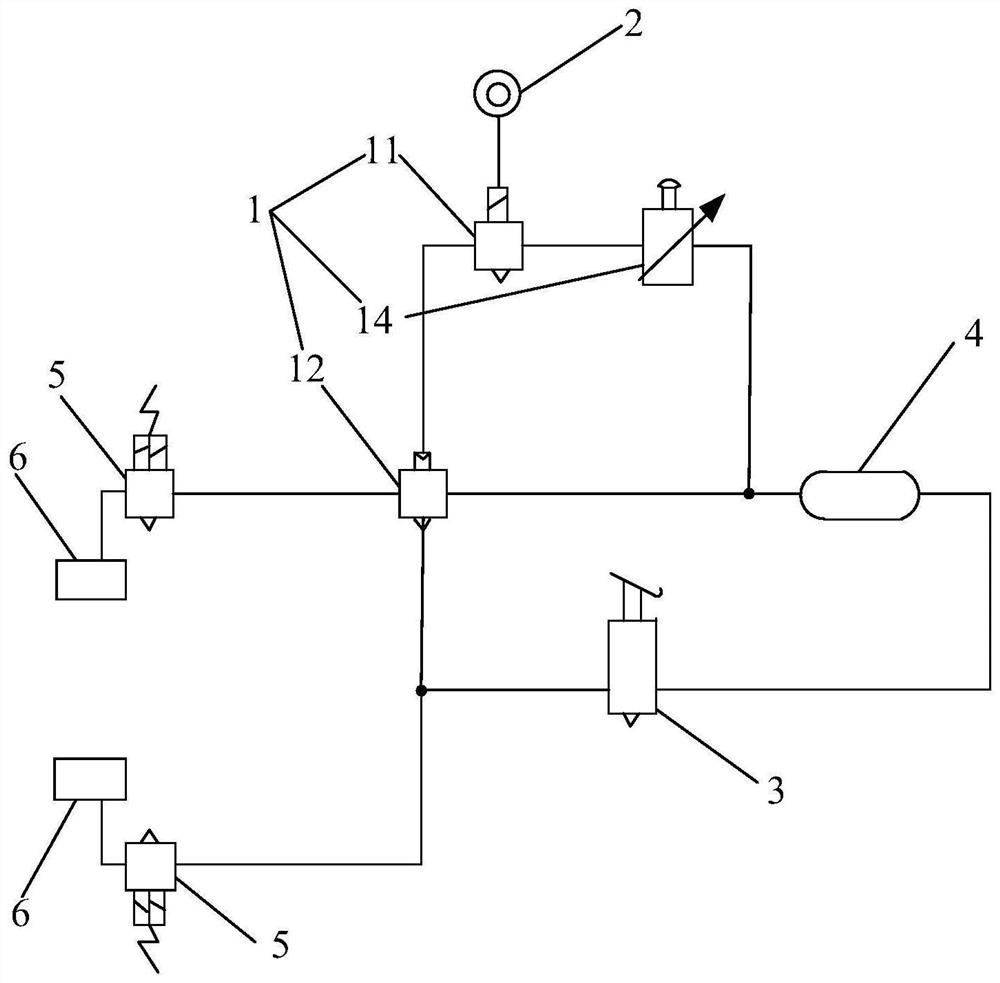
[0048] Please refer to figure 2 , the vehicle brake detection system in this embodiment includes a gas valve module 1, a switch module 2 and a detection module. Wherein, the air valve module 1 includes a first valve body 11 and a second valve body 12 . One end of the first valve body 11 communicates with the gas storage tank 4 , and the other end of the first valve body 11 communicates with the second valve body 12 for transferring the gas in the gas storage tank 4 to the second valve body 12 . The switch module 2 is electrically connected to the first valve body, and is used to control the conduction or closure of the first valve body 11. When the first valve body 11 is on, the gas in the gas storage tank 4 can be transmitted to the second Two valve bodies 12. When the first valve body 11 is closed, the gas in the air reservoir 4 cannot be transmitted to the second valve body 12 through the first valve body 11 .
[0049] The second valve body 12 has a plurality of ports f...
Embodiment 2
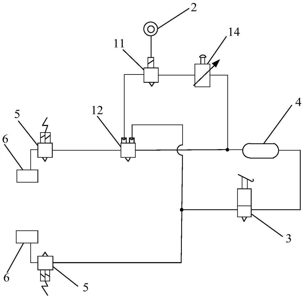
[0070] The vehicle braking detection system in this embodiment includes an air valve module 1 , a switch module 2 and a detection module. Wherein, the structures of the switch module 2 and the detection module are the same as those of the switch module 2 and the detection module in the first embodiment, and will not be repeated in this embodiment. The air valve module 1 in this embodiment is different from the air valve module 1 in the first embodiment. The air valve module 1 in this embodiment not only includes a first valve body 11 and a second valve body 12 , but also includes a third valve body 13 connected in series between the first valve body 11 and the second valve body 12 .
[0071] Specifically, please refer to Figure 5 , the first port of the third valve body 13 communicates with the other end of the first valve body 11 , and the second port of the third valve body 13 communicates with the control port of the second valve body 12 . The third valve body 13 is used...
Embodiment 3
[0076] The vehicle braking detection system in this embodiment includes an air valve module 1 , a switch module 2 and a detection module. Wherein, the structures of the switch module 2 and the detection module are the same as those of the switch module 2 and the detection module in the first embodiment, and will not be repeated in this embodiment. The air valve module 1 in this embodiment is different from the air valve module 1 in the first embodiment. Specifically, the air valve module 1 in this embodiment only includes the first valve body 11, but does not include the second valve body.
[0077] Specifically, please refer to Image 6 The first valve body 11 is electrically connected to the switch module 2, and one end of the first valve body 11 communicates with the air reservoir 4, and the other end of the first valve body 11 communicates with the ABS solenoid valve 5 on the vehicle side.
[0078] When it is necessary to detect the braking performance of the vehicle, the...
PUM
 Abstract
Description
Claims
Application Information
 - R&D
- Intellectual Property
- Life Sciences
- Materials
- Tech Scout
- Unparalleled Data Quality
- Higher Quality Content
- 60% Fewer Hallucinations
Browse by: Latest US Patents, China's latest patents, Technical Efficacy Thesaurus, Application Domain, Technology Topic, Popular Technical Reports.
© 2025 PatSnap. All rights reserved.Legal|Privacy policy|Modern Slavery Act Transparency Statement|Sitemap|About US| Contact US: help@patsnap.com


