Low Profile, Compact Linear and Circular Polarization Filter Antennas with High Selectivity

A high-selectivity, filtering antenna technology, applied in the direction of antenna, antenna grounding device, antenna grounding switch structure connection, etc., can solve the problems of no filter structure, low gain, large lateral size, etc., achieve excellent filtering performance, realize line Effect of polarization and circular polarization, compact size

Active Publication Date: 2021-02-09
CHONGQING UNIV
View PDF3 Cites 3 Cited by
  • Summary
  • Abstract
  • Description
  • Claims
  • Application Information

AI Technical Summary

Problems solved by technology

The first method is to use the filter directly as the feed network of the antenna to achieve filtering performance. This method can reduce the interconnection loss of the traditional method and reduce the weight of the RF front-end, but this method directly increases the filter antenna to a large extent. size and design complexity
The second method is to use the antenna as the last resonator and impedance load of the filter, so that the antenna has both filtering and radiation functions, but this usually requires coupling and cascading multiple resonators, resulting in a large lateral size
The third method optimizes the antenna, such as etching grooves on the radiator, and adopts a defective ground structure, so that the antenna can exhibit filtering performance without a separate filter structure, but this usually increases its gain ratio Lower when no filter performance is loaded
However, this usually requires the use of multi-layer structures or the introduction of air layers, which will lead to complex structures, high profiles, high costs and difficult processing

Method used


Image

  • Low Profile, Compact Linear and Circular Polarization Filter Antennas with High Selectivity
  • Low Profile, Compact Linear and Circular Polarization Filter Antennas with High Selectivity
  • Low Profile, Compact Linear and Circular Polarization Filter Antennas with High Selectivity

Examples


specific Embodiment

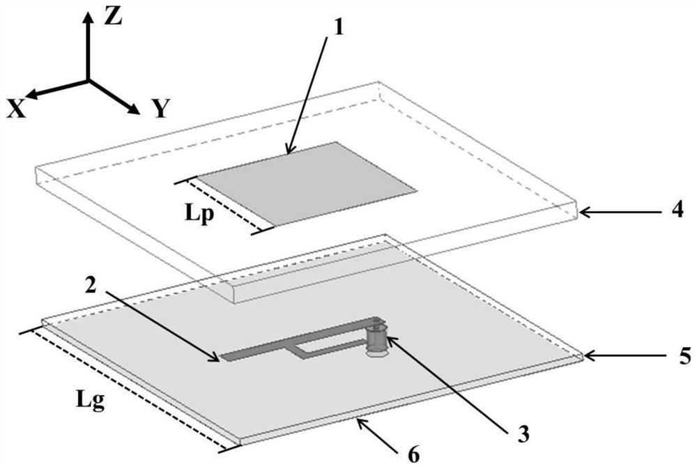
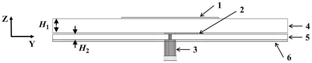
[0059] figure 1 It is a three-dimensional view of the overall structure of the low-profile, compact linearly polarized filter antenna with high selectivity in the present invention. The low-profile, compact linearly polarized filter antenna with high selectivity in the present invention includes a radiation patch 1, Feeder 2, coaxial cable 3, two dielectric substrates 4, 5, and grounding plate 6.

[0060] Wherein, a square radiating patch 1 is printed on the upper surface of the upper dielectric substrate 4, and the presence of the radiating patch can make the antenna exhibit a side-firing characteristic;

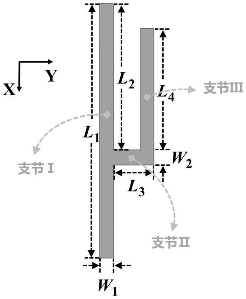
[0061] The feeder 2 is composed of three branches located on the upper surface of the lower dielectric substrate 5, wherein the interaction between the branch I and the radiation patch 1 can generate a high-frequency zero point, thereby achieving excellent filtering performance in the upper stop band; The combination of section II and branch III forms an L-shaped branch. T...


PUM

PropertyMeasurementUnit
lengthaaaaaaaaaa
thicknessaaaaaaaaaa
lengthaaaaaaaaaa

Abstract

The invention relates to a low-profile, compact linear polarization and circular polarization filter antenna with high selectivity, which belongs to the field of antenna technology. Both filter antennas include a radiation patch, a feeder part, a coaxial cable, and two dielectrics Substrate and grounding plate; two dielectric substrates are stacked, the radiation patch is arranged on the upper surface of the upper dielectric substrate, the feeder part is arranged on the upper surface of the lower dielectric substrate, and the grounding plate is arranged on the lower surface of the lower dielectric substrate; two models The only difference in the filter antenna is the feeder part. The linearly polarized filter antenna uses an inverted H-shaped feeder, which can interact with the radiation patch to generate two zero points to achieve excellent filtering performance. The circularly polarized filter antenna retains the above-mentioned linear polarization. At the same time as the feeder, an additional T-shaped feeder is used to produce circular polarization filtering performance. That is to say, the linear polarization and circular polarization antennas proposed by the present invention have simple structures and good frequency selection and out-of-band suppression characteristics.

Description

technical field [0001] The invention belongs to the technical field of antennas, and relates to a low profile, compact linear polarization and circular polarization filter antenna with high selectivity. Background technique [0002] With the rapid development of wireless communication, the research of various wireless communication devices is constantly evolving towards the direction of compactness, low profile and integration. As a new antenna design method that takes into account both the functions of the filter and the antenna, filter antenna design has entered people's field of vision, and has begun to receive widespread attention. The joint design of antenna and filter is advocated, so that the filter antenna has radiation, impedance matching, Adjacent channel anti-interference, filtering and balance conversion functions. The filter antenna has excellent frequency selection characteristics and good out-of-band suppression ability in frequency and gain response, which i...

Claims


Application Information

Patent Timeline
Patent Type & Authority Patents(China)
IPC IPC(8): H01Q1/38H01Q1/48H01Q1/50H01Q5/10H01Q5/307H01Q5/335H01Q15/24H01Q15/00
CPCH01Q1/38H01Q1/48H01Q1/50H01Q15/0053H01Q15/24H01Q5/10H01Q5/307H01Q5/335
Inventor 唐明春李大疆刘国汪洋胡坤志李梅理查德·齐奥尔科夫斯基
Owner CHONGQING UNIV
Why Eureka
Try Eureka