
Distribution cabinet

A technology for power distribution cabinets and cabinets, which is applied to the substation/power distribution device shell, electrical components, substation/switch layout details, etc., which can solve problems such as ineffective heat dissipation, short circuit of power components, and fire of power components, so as to prevent The effect of rainwater entering the cabinet and accelerating the air velocity

Active Publication Date: 2019-12-20
深圳市奥通自动化有限公司
View PDF9 Cites 9 Cited by
  • Summary
  • Abstract
  • Description
  • Claims
  • Application Information

AI Technical Summary

Problems solved by technology

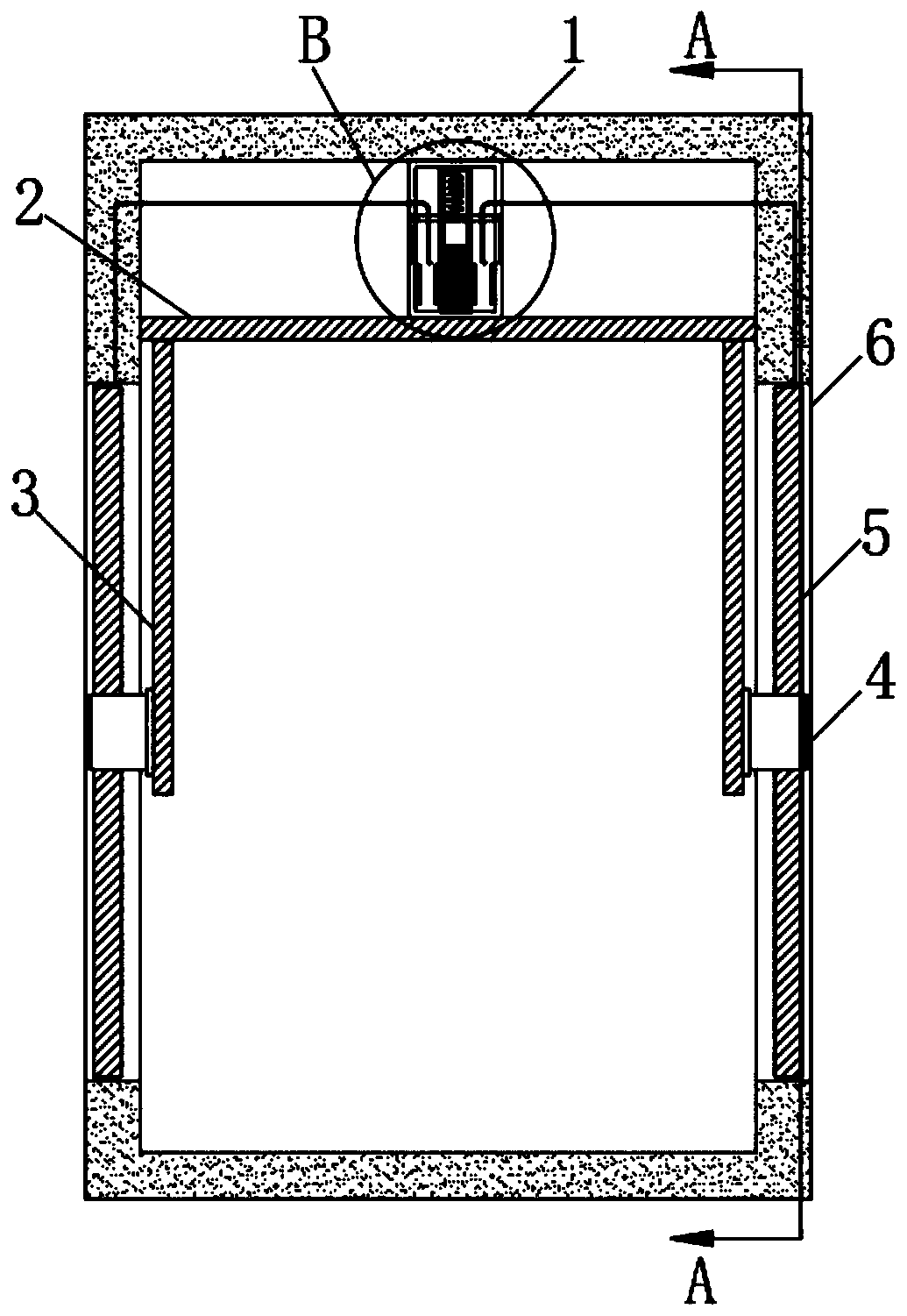
[0003] 1. The power components in the power distribution cabinet will generate a lot of heat when they work. Moreover, in the open air environment, when encountering high temperature weather, the temperature in the power distribution cabinet will be higher, and it is easy to burn out the internal parts of the power distribution cabinet. Power components will cause harm to the transmission of communication circuits. In severe cases, the internal power components may catch fire and cause a fire. However, the existing power distribution cabinets generally only have some small ventilation openings on the side walls of the cabinet. The interior of the electric cabinet is still in a nearly airtight state, and the heat dissipation effect is not obvious;
[0004] 2. After opening some vents in the power distribution cabinet, in rainy days, rainwater will easily enter the power distribution cabinet, which will easily cause a short circuit of the internal power components, interrupt the transmission of power, and bring inconvenience to the communication work

Method used


Image

  • Distribution cabinet
  • Distribution cabinet
  • Distribution cabinet

Examples


Embodiment Construction

[0023] The following will clearly and completely describe the technical solutions in the embodiments of the present invention with reference to the accompanying drawings in the embodiments of the present invention. Obviously, the described embodiments are only some, not all, embodiments of the present invention.

[0024] In describing the present invention, it should be understood that the terms "upper", "lower", "front", "rear", "left", "right", "top", "bottom", "inner", " The orientation or positional relationship indicated by "outside", etc. is based on the orientation or positional relationship shown in the drawings, and is only for the convenience of describing the present invention and simplifying the description, rather than indicating or implying that the referred device or element must have a specific orientation, so as to Specific orientation configurations and operations, therefore, are not to be construed as limitations on the invention.

[0025] refer to Figure ...


PUM


Abstract

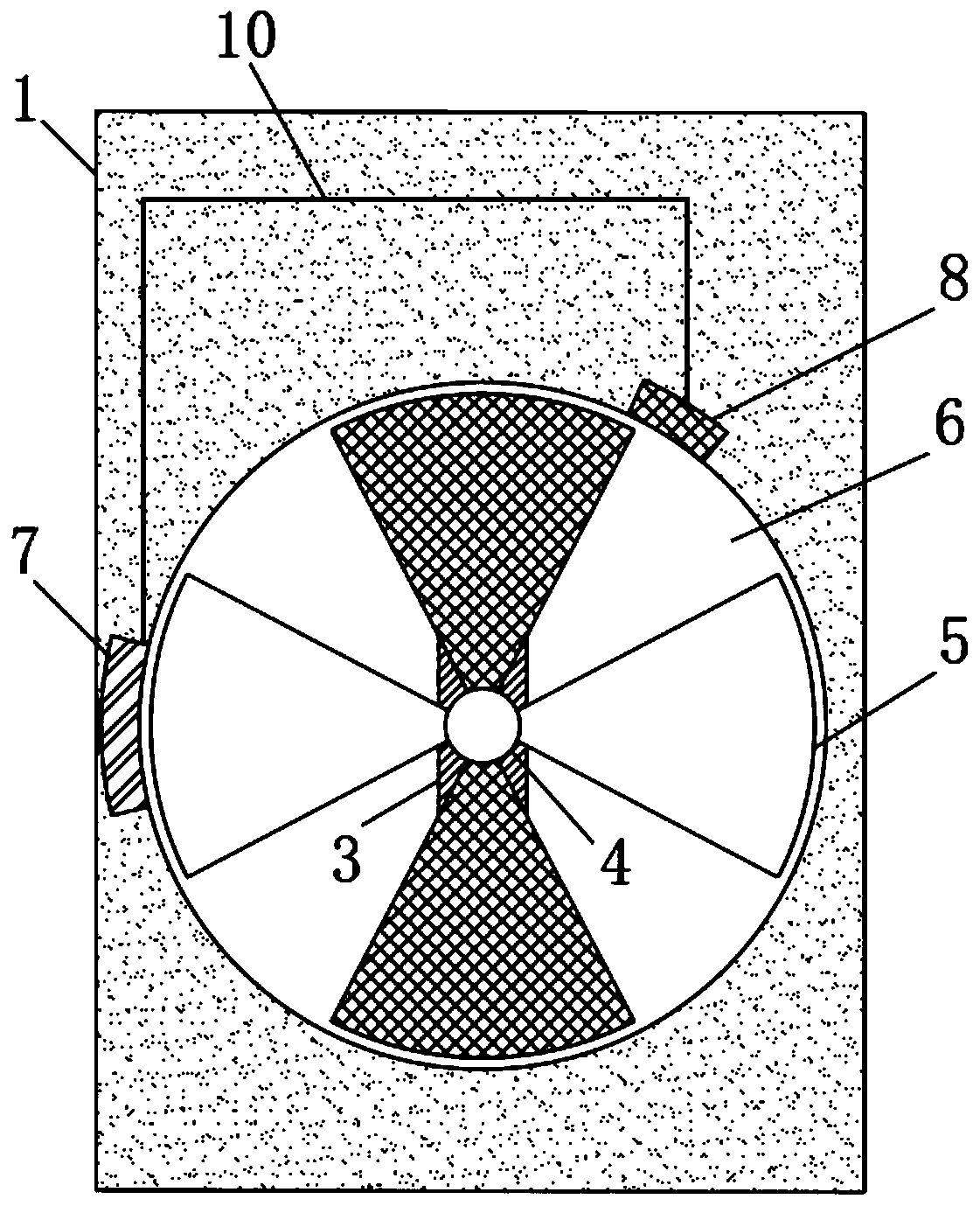
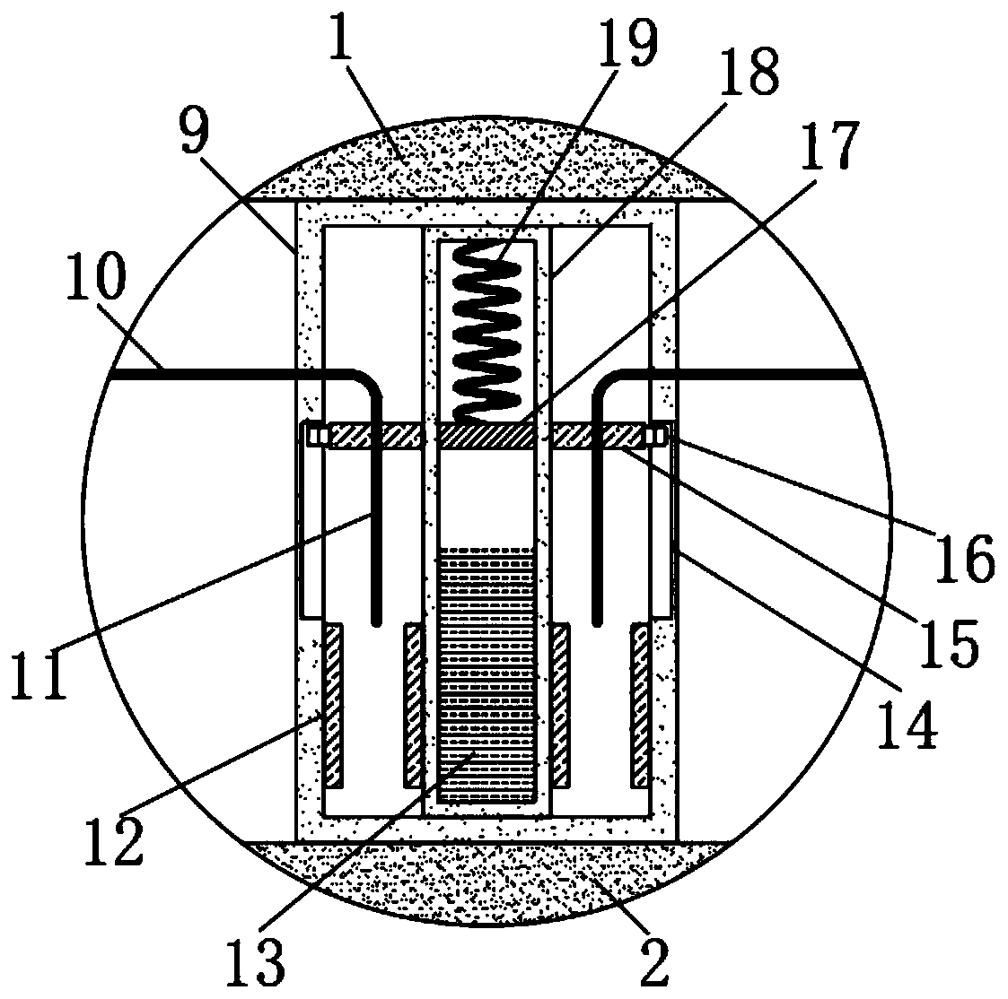
The invention discloses a distribution cabinet, which includes a cabinet body, wherein a heat dissipation mechanism is disposed in the cabinet body and includes a fixing plate fixedly connected to aninner wall of the cabinet body close to the upper end. A mounting box is fixedly connected to the upper wall of the fixing plate. A placing box is fixedly connected to the inner bottom of the mountingbox. The placing box is filled with a cooling liquid. A magnetic sliding plate is elastically connected to the upper inner wall of the placing box through a first memory metal sheet. Two permanent magnets that attract the magnetic sliding plate by opposite poles are slidably connected with the inner wall of the mounting box. Copper frames are fixedly inserted into the side walls of the two permanent magnets. The opposite side walls of the mounting box and the placing box are fixedly connected with two magnetic plates attracting each other by opposite poles. The inside of the distribution cabinet can be automatically cooled according to a temperature change, so as to ensure that power components in the cabinet body cannot be damaged by high temperature, and prevent rainwater from enteringthe cabinet body to ensure that the power components in the cabinet body cannot be short circuited.

Description

technical field [0001] The invention relates to the technical field of power communication equipment, in particular to a power distribution cabinet. Background technique [0002] With the continuous development of power communication technology, the use of power distribution cabinets is becoming more and more extensive. The power distribution cabinets are mainly used to hold some power components. Most of the power distribution The electric cabinet has the following problems: [0003] 1. The power components in the power distribution cabinet will generate a lot of heat when they work. Moreover, in the open air environment, when encountering high temperature weather, the temperature in the power distribution cabinet will be higher, and it is easy to burn out the internal parts of the power distribution cabinet. Power components will cause harm to the transmission of communication circuits. In severe cases, the internal power components may catch fire and cause a fire. Howeve...

Claims


Application Information

Patent Timeline
IPC IPC(8): H02B1/30H02B1/56H02B1/28
CPCH02B1/28H02B1/30H02B1/565
Inventor 朱蛟龙
Owner 深圳市奥通自动化有限公司
Learn More