
PWM method for electric vehicle motor inverter

A modulation method, electric vehicle technology, applied in the direction of AC motor control, irreversible DC power input conversion to AC power output, electrical components, etc.

Active Publication Date: 2019-12-20
SHANGHAI DAJUN TECH
View PDF7 Cites 12 Cited by
  • Summary
  • Abstract
  • Description
  • Claims
  • Application Information

AI Technical Summary

Problems solved by technology

[0010] The technical problem to be solved by the present invention is to provide a PWM modulation method for electric vehicle motor inverters. This method overcomes the defects of traditional motor inverter modulation, effectively reduces the common-mode voltage output amplitude at the time of zero vector, and suppresses The current amplitude of the motor shaft increases the service life of the motor bearing, reduces the vibration and noise output of the motor inverter system, and improves the driving quality of the vehicle

Method used


Image

  • PWM method for electric vehicle motor inverter
  • PWM method for electric vehicle motor inverter
  • PWM method for electric vehicle motor inverter

Examples


Embodiment Construction

[0066] The PWM modulation method that the present invention is used for electric vehicle motor inverter comprises the following steps:

[0067] Step 1. Set the modulation ratio of the inverter as:

[0068] MI=V s / (0.6366U DC ) (1)

[0069] Among them, V s is the motor stator reference voltage vector, U DC is the DC bus voltage;

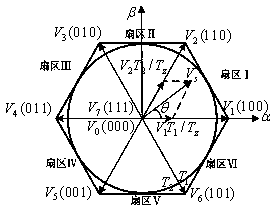
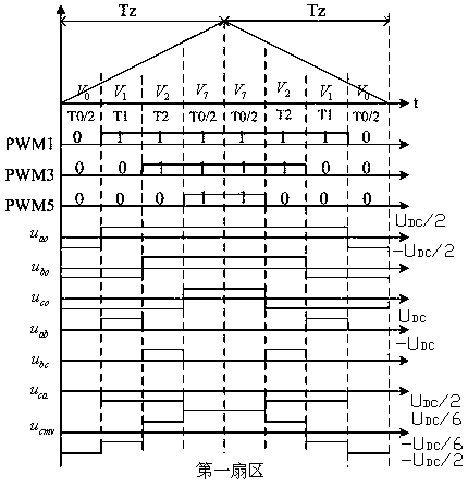
[0070] The NZPWM modulation method is used to perform PWM modulation on the inverter, and its reference voltage vector synthesis selects two adjacent non-zero opposite vectors, and makes them act for the same time to be equivalent to the role of the zero vector, for example, as figure 2 As shown, the reference voltage vector V s In the first sector, using the non-zero voltage vector V 1 , V 2 Used to synthesize the reference voltage vector V s , vector V 3 and V 6 Respectively act the same time to replace the zero vector;

[0071] Using the principle of volt-second balance, calculate the action time of each voltage vector:

[0072]

...


PUM


Abstract

The invention discloses a PWM method for an electric vehicle motor inverter. The method comprises the steps of performing PWM on the inverter by an NZPWM method, and reasonably arranging a reference voltage vector synthesis sequence and a PWM pulse action mode of each section; correcting a three-phase modulation wave generated by NZPWM to obtain an inverter boundary modulation ratio parameter, andrespectively executing NZPWM and SVPWM according to the modulation ratio parameter; performing over-modulation on the inverter by a discrete PWM method after a voltage vector enters an over-modulation region from a linear modulation region, dividing the over-modulation region into two regions, and setting a modulation ratio of lower boundaries of the two regions; and executing discrete PWM of thetwo over-modulation regions according to the modulation ratio to obtain an expected PWM waveform. By the method, the common-mode voltage output amplitude at zero vector is effectively reduced, motorshaft current amplitude is suppressed, the service lifetime of a motor bearing is prolonged, the vibration and the noise output of a motor inversion system are reduced, and the driving quality of thewhole vehicle is improved.

Description

technical field [0001] The invention relates to the technical field of motor control, in particular to a PWM modulation method for an electric vehicle motor inverter. Background technique [0002] Usually in the modulation of the embedded three-phase permanent magnet synchronous motor (PMSM) driving the inverter of the electric vehicle, the pulse width modulation (PWM) strategy is used to realize the control of the motor stator voltage space vector. figure 1 The structure diagram of the three-phase inverter is shown, and the PWM methods for modulating it include sinusoidal pulse width modulation (SPWM), space voltage vector pulse width modulation (SVPWM), and discrete PWM modulation. If the inverter modulation ratio is defined as: [0003] MI=V s / (0.6366U DC ) (1) [0004] Among them, V s is the motor stator reference voltage vector, U DC is the DC bus voltage. [0005] The modulation wave of SPWM is a three-phase sinusoidal signal, and its maximum linear modulation ...

Claims


Application Information

Patent Timeline
IPC IPC(8): H02P27/08H02P27/12H02M7/42H02M7/5387
CPCH02M7/42H02M7/53875H02P27/085H02P27/12H02M7/53876
Inventor 吴平仿陈双黄洪剑
Owner SHANGHAI DAJUN TECH
Learn More