A special workbench for engineering cost

A project cost and workbench technology, applied in applications, home appliances, legs of general furniture, etc., can solve the problems of wasting time, wasting energy, and inconvenient recording.

Inactive Publication Date: 2021-07-06
安徽新起点建设项目管理有限公司
View PDF13 Cites 2 Cited by
  • Summary
  • Abstract
  • Description
  • Claims
  • Application Information

AI Technical Summary

Problems solved by technology

[0003] In order to overcome the disadvantages of wasting time and energy in the process of querying drawings, and may need to record some data at any time during the construction process, since there is no workbench on the construction site, it is inconvenient to record, resulting in low work efficiency. The technical problem to be solved is: to provide a special workbench for engineering cost that saves time and effort and is convenient for recording

Method used


Image

  • A special workbench for engineering cost
  • A special workbench for engineering cost
  • A special workbench for engineering cost

Examples


Embodiment 1

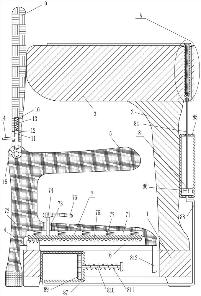
[0016] A special workbench for engineering cost, such as figure 1 As shown, it includes a back-shaped base 1, a support plate 2, a table plate 3, a slider 4, a seat cushion 5 and a clamping device 7, and the top right side of the back-shaped base 1 is provided with a support plate 2, and the back-shaped base 1 is welded The connection method is connected with the support plate 2, the top of the support plate 2 is provided with a table plate 3, and the front and rear parts on the left side of the top of the back-shaped base 1 are provided with sliders 4, and the back-shaped base 1 is connected with the slider 4 by welding There are chute 6 on the front and rear sides of the right bottom of the seat cushion 5, the slider 4 is located in the chute 6, the seat cushion 5 is located above the return-shaped base 1, and a clamping device is provided between the seat cushion 5 and the chute 6 7.

Embodiment 2

[0018] A special workbench for engineering cost, such as figure 1 As shown, it includes a return-shaped base 1, a support plate 2, a table plate 3, a slider 4, a seat cushion 5 and a clamping device 7, a support plate 2 is provided on the right side of the top of the return-shaped base 1, and a Table board 3, slide block 4 is arranged on both front and rear parts on the left side of the top of the back-shaped base 1, and chute 6 is provided on the front and rear sides of the bottom right side of the seat cushion 5, the slide block 4 is located in the chute 6, and the seat cushion 5 is located on the A clamping device 7 is provided between the seat cushion 5 and the chute 6 above the return-shaped base 1 .

[0019] The clamping device 7 includes a slide bar 74, a handle 75, a tooth plate 76 and a first spring 77, the top of the chute 6 has a first opening 71, the top of the slider 4 has a clamping hole 72, and the bottom of the seat cushion 5 has an opening. There are two open...

Embodiment 3

[0021] A special workbench for engineering cost, such as Figure 1-3 As shown, it includes a return-shaped base 1, a support plate 2, a table plate 3, a slider 4, a seat cushion 5 and a clamping device 7, a support plate 2 is provided on the right side of the top of the return-shaped base 1, and a Table board 3, slide block 4 is arranged on both front and rear parts on the left side of the top of the back-shaped base 1, and chute 6 is provided on the front and rear sides of the bottom right side of the seat cushion 5, the slide block 4 is located in the chute 6, and the seat cushion 5 is located on the A clamping device 7 is provided between the seat cushion 5 and the chute 6 above the return-shaped base 1 .

[0022] The clamping device 7 includes a slide bar 74, a handle 75, a tooth plate 76 and a first spring 77, the top of the chute 6 has a first opening 71, the top of the slider 4 has a clamping hole 72, and the bottom of the seat cushion 5 has an opening. There are two o...


PUM


Abstract

The invention relates to a workbench, in particular to a special workbench for engineering cost. The technical problem to be solved is to provide a special workbench for engineering cost which saves time and labor and is convenient for recording. The technical solution of the present invention is: a special workbench for engineering cost, including a back-shaped base, etc.; Both are provided with slide blocks, and the front and rear sides of the bottom right side of the seat cushion are provided with chute, and the slide block is located in the chute. The present invention, through the function of the table board and the seat cushion, can avoid the inconvenience of the staff when they need to record when working outdoors, and through the function of the first U-shaped movable plate, it can block the wind and blow away the drawing paper on the workbench without the need for staff Keep pressing the drawings with your hands, and by adjusting the angle of the backboard, the staff can work more comfortably, avoiding backaches and backaches during long-term work on the workbench, thereby improving work efficiency.

Description

technical field [0001] The invention relates to a workbench, in particular to a special workbench for engineering cost. Background technique [0002] During the construction process, the construction unit will receive many drawings issued by the design institute. These drawings need to be used repeatedly during the construction process. There are many inconveniences in the process of consulting the drawings. It is a waste of time and energy to go back and forth between the engineering drawing wall chart rack and the desk several times, and some data may need to be recorded at any time during the construction process. Since there is no workbench on the construction site, it is inconvenient to record, so lead to low work efficiency. Contents of the invention [0003] In order to overcome the disadvantages of wasting time and energy in the process of querying drawings, and may need to record some data at any time during the construction process, since there is no workbench o...

Claims


Application Information

Patent Timeline
Patent Type & Authority Patents(China)
IPC IPC(8): A47B83/02A47B27/00A47B27/18A47C7/40A47C7/00A47B13/08
CPCA47B13/08A47B27/00A47B27/18A47B83/02A47B2200/0001A47B2200/11A47C7/002A47C7/40A47B83/021
Inventor 廖明兰
Owner 安徽新起点建设项目管理有限公司
Why Eureka
Try Eureka