Iron scrap separation equipment for hardware production

A technology for separating equipment and iron filings, applied in the field of separation equipment for hardware production, can solve problems such as backache of iron filings, lowering the separation efficiency of iron filings, etc., and achieve the effects of preventing backache, good separation, and improving efficiency.

Active Publication Date: 2020-09-11
TIANJIN SAIXIANG M&E ENG CO LTD
View PDF11 Cites 0 Cited by
  • Summary
  • Abstract
  • Description
  • Claims
  • Application Information

AI Technical Summary

Problems solved by technology

[0003] In order to overcome the shortcoming that people hold a magnet for a long time to bend over to separate iron filings, which may easily cause back pain and reduce the efficiency of iron filing separation, the technical problem to be solved is to provide a device that can prevent back pain and improve separation efficiency. Iron filings separation equipment for hardware production

Method used


Image

  • Iron scrap separation equipment for hardware production
  • Iron scrap separation equipment for hardware production
  • Iron scrap separation equipment for hardware production

Examples


Embodiment 1

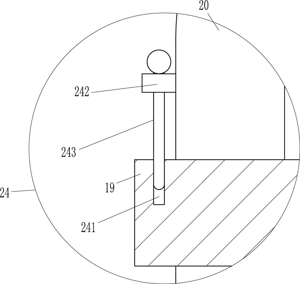
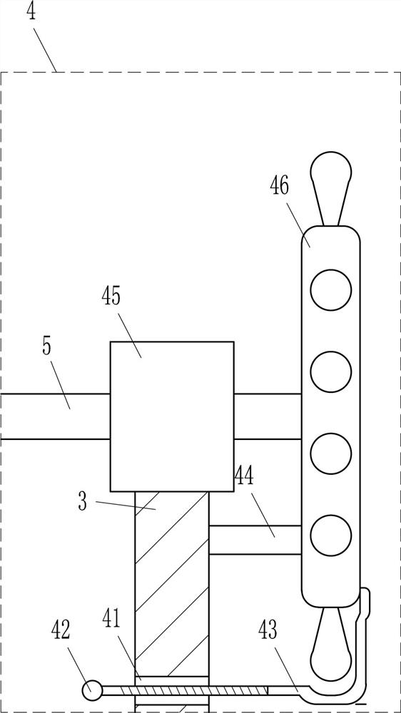
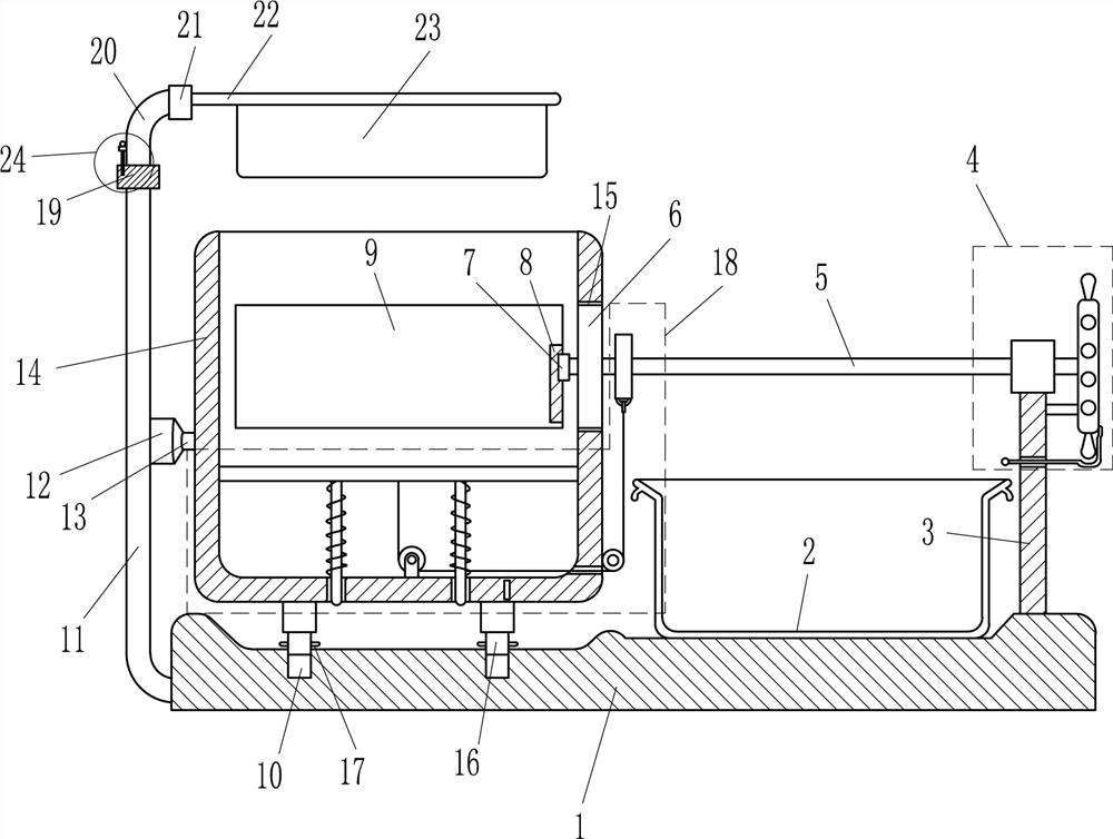
[0022] A kind of iron scrap separation equipment for hardware production, such as Figure 1-4 As shown, it includes a bottom plate 1, a collection frame 2, a right frame 3, a rotating device 4, a guide rod 5, a circular baffle 6, a slider 7, a slide rail 8, an electromagnet 9, a left frame 11, and a first bearing seat 12. The first rotating shaft 13, the frame body 14, the telescopic rod 16 and the block 17. There are two slots 10 on the left side of the top of the bottom plate 1. The telescopic rod 16 is slidably located in the slot 10. Both sides are provided with clamping blocks 17, and a frame body 14 capable of placing iron filings is installed between the top ends of the left and right two telescopic rods 16, and the upper part of the right side of the frame body 14 has a circular hole 15 that acts as a guide to support The left frame 11 of action is arranged on the left side of the base plate 1, and the bottom of the right side of the left frame 11 is equipped with a fi...

Embodiment 2

[0024] A kind of iron scrap separation equipment for hardware production, such as Figure 1-4 As shown, it includes a bottom plate 1, a collection frame 2, a right frame 3, a rotating device 4, a guide rod 5, a circular baffle 6, a slider 7, a slide rail 8, an electromagnet 9, a left frame 11, and a first bearing seat 12. The first rotating shaft 13, the frame body 14, the telescopic rod 16 and the block 17. There are two slots 10 on the left side of the top of the bottom plate 1. The telescopic rod 16 is slidably located in the slot 10. Both sides are provided with clamping blocks 17, and a frame body 14 capable of placing iron filings is installed between the top ends of the left and right two telescopic rods 16, and the upper part of the right side of the frame body 14 has a circular hole 15 that acts as a guide to support The left frame 11 of action is arranged on the left side of the base plate 1, and the bottom of the right side of the left frame 11 is equipped with a firs...

Embodiment 3

[0027] A kind of iron scrap separation equipment for hardware production, such as Figure 1-4 As shown, it includes a bottom plate 1, a collection frame 2, a right frame 3, a rotating device 4, a guide rod 5, a circular baffle 6, a slider 7, a slide rail 8, an electromagnet 9, a left frame 11, and a first bearing seat 12. The first rotating shaft 13, the frame body 14, the telescopic rod 16 and the block 17. There are two slots 10 on the left side of the top of the bottom plate 1. The telescopic rod 16 is slidably located in the slot 10. Both sides are provided with clamping blocks 17, and a frame body 14 capable of placing iron filings is installed between the top ends of the left and right two telescopic rods 16, and the upper part of the right side of the frame body 14 has a circular hole 15 that acts as a guide to support The left frame 11 of action is arranged on the left side of the base plate 1, and the bottom of the right side of the left frame 11 is equipped with a fi...


PUM


Abstract

The invention relates to separation equipment for hardware production, in particular to scrap iron separation equipment for hardware production. The scrap iron separation equipment for hardware production which can be used for preventing back pain and can be used for improving separation efficiency is provided. The scrap iron separation equipment for hardware production comprises a bottom plate, acollection frame, a right rack, a rotation device, a guide rod, a round baffle plate, a sliding block and a sliding rail, wherein two slots are formed in a left side of the top of the bottom plate, atelescopic rod is arranged in the slots in a sliding way, clamping blocks are arranged at a left side and a right side of the telescopic rod, and a frame is arranged between top ends of a left telescopic rod and a right telescopic and can be used for placing scrap iron. An electromagnet can rotate to absorb the scrap iron by the rotation device, people do not need to handhold a magnet to separatethe scrap iron, so that the back pain can be prevented, and the scrap iron separation efficiency can be improved; and by a lifting device, the scrap iron can be separated very well, and the scrap iron separation efficiency can be accelerated.

Description

technical field [0001] The invention relates to a separation device for hardware production, in particular to a separation device for iron filings for hardware production. Background technique [0002] After the production of hardware, a large amount of iron filings will be produced, and there are some other metal filings in the iron filings. For this reason, the iron filings need to be separated. At present, when people separate the iron filings, people usually hold a magnet and bend down to separate the iron filings. Separation, and people bend over to separate iron filings for a long time will easily cause back pain, which will reduce the separation efficiency of iron filings. In order to improve the separation efficiency of iron filings, people will use electromagnets to separate iron filings, and the electromagnet is adsorbing There will be some other metal filings sticking to the iron filings, which will hinder the separation of iron filings. Contents of the inventio...

Claims


Application Information

Patent Timeline
Patent Type & Authority Patents(China)
IPC IPC(8): B03C1/02
CPCB03C1/02
Inventor 廖子宁
Owner TIANJIN SAIXIANG M&E ENG CO LTD
Why Eureka
Try Eureka