Anti-loosening and anti-electric-shock socket

An anti-electric shock and socket technology, which is applied in the direction of preventing contact with live contacts, devices, circuits, electrical components, etc., can solve the problems of easy loosening of sockets and plugs, electric shock, etc., and achieve good anti-loosening effect, good isolation and anti-shock , The pull-out process is convenient and easy

Inactive Publication Date: 2019-12-03
新昌县希克自动化设备有限公司
View PDF7 Cites 8 Cited by
  • Summary
  • Abstract
  • Description
  • Claims
  • Application Information

AI Technical Summary

Problems solved by technology

[0004] The purpose of the present invention is to solve the problem in the prior art that the connection between the socket and the plug is easy to loosen and cause an electric shock, and proposes an anti-loose and anti-electric shock socket

Method used


Image

  • Anti-loosening and anti-electric-shock socket
  • Anti-loosening and anti-electric-shock socket
  • Anti-loosening and anti-electric-shock socket

Examples


Embodiment 1

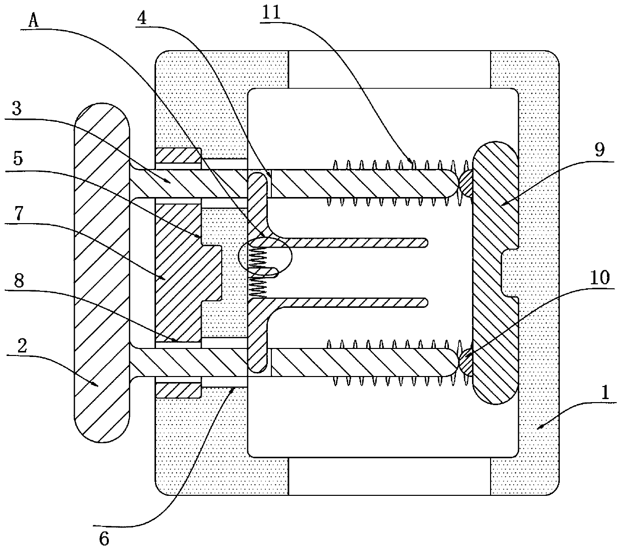
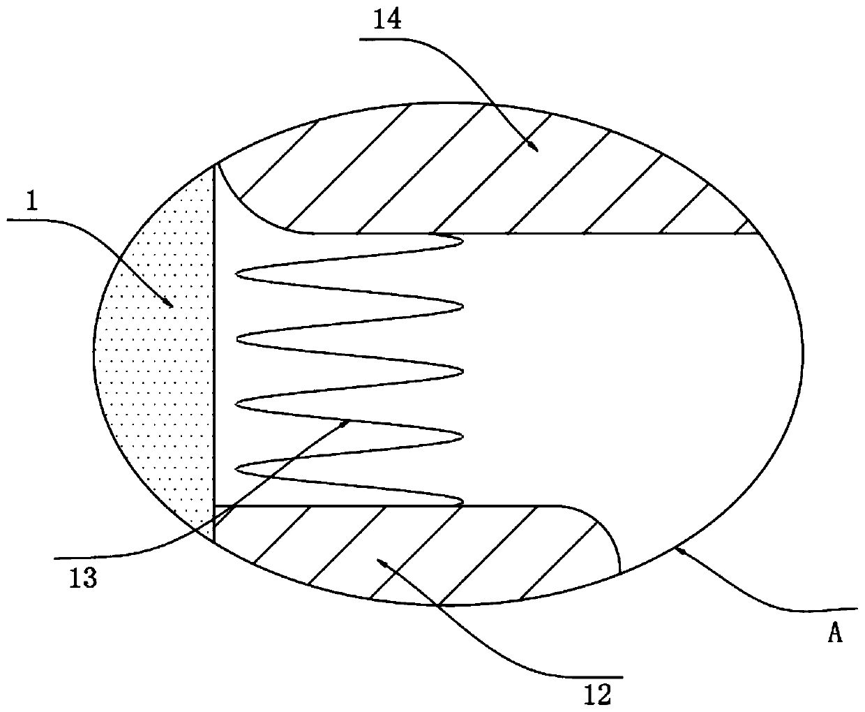
[0025] refer to Figure 1-2 , an anti-loose and anti-shock socket, comprising a socket shell 1, the outer wall of the socket shell 1 is provided with a mounting groove 5, and the inner bottom of the mounting groove 5 is symmetrically provided with two slots 6 communicating with the inside of the socket shell 1, and the slot 6 It is an arc-shaped slot, and the connecting column 3 can rotate along the inner wall of the slot 6. The inner bottom of the installation slot 5 is connected to the rotating plate 7 through the rotation of the torsion spring, and the side wall of the rotating plate 7 is provided with two symmetrically arranged sockets 8. The inner wall of one end of the socket housing 1 far away from the rotating plate 7 is provided with an electrical connection device for energizing, and the inner wall of the end of the socket housing 1 close to the rotating plate 7 is provided with a locking device for preventing the plug from getting loose.

[0026] An anti-loosening p...

Embodiment 2

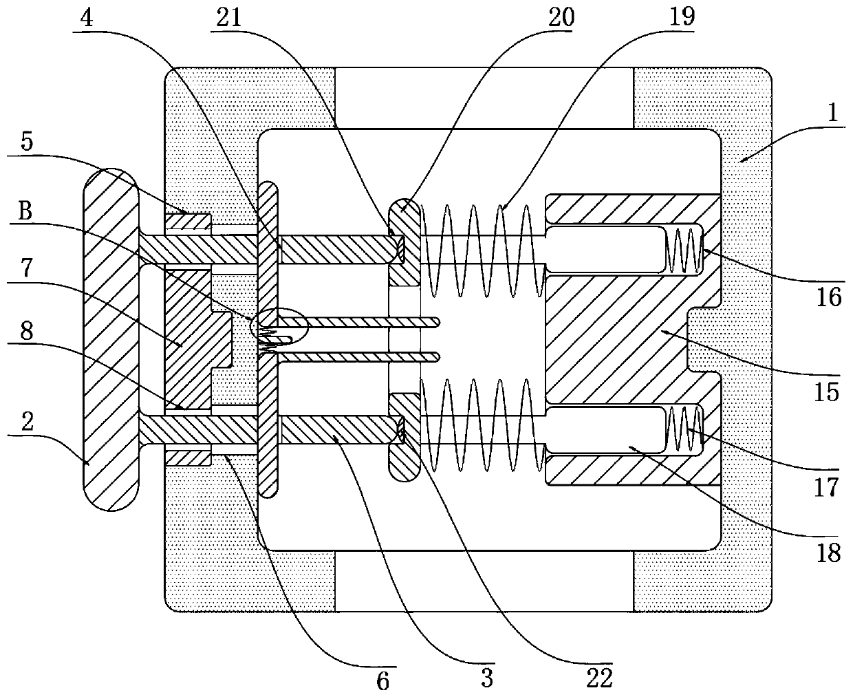
[0032] refer to Figure 3-5, an anti-loose and anti-shock socket, comprising a socket shell 1, the outer wall of the socket shell 1 is provided with a mounting groove 5, and the inner bottom of the mounting groove 5 is symmetrically provided with two slots 6 communicating with the inside of the socket shell 1, and the slot 6 It is an arc-shaped slot, and the connecting column 3 can rotate along the inner wall of the slot 6. The inner bottom of the installation slot 5 is connected to the rotating plate 7 through the rotation of the torsion spring, and the side wall of the rotating plate 7 is provided with two symmetrically arranged sockets 8. The inner wall of one end of the socket housing 1 far away from the rotating plate 7 is provided with an electrical connection device for energizing, and the inner wall of the end of the socket housing 1 close to the rotating plate 7 is provided with a locking device for preventing the plug from getting loose.

[0033] An anti-loosening pl...


PUM


Abstract

The invention discloses an anti-loosening and anti-electric-shock socket comprising a socket shell. The outer wall of the socket shell is provided with a mounting groove. The inner bottom of the mounting groove is symmetrically provided with two inserting grooves which are communicated with the internal part of the socket shell. A rotating plate is rotatably connected on inner bottom of the mounting groove through a torsion spring. The side wall of the rotating plate is provided with two symmetrically arranged jacks in a penetration way. The inner wall of one end of the socket shell away fromthe rotating plate is provided with an electric receiving device for electrifying. The inner wall of one end of the socket shell near the rotating plate is provided with a clamping device for preventing the connecting plug from loosening. The advantages are that the intensity of the induction magnetic field generated by the first coil is greatly enhanced through the insertion of the power receiving column, then the attraction force received by the limiting rod is increased, the limiting rod can overcome the elastic force of the return spring and slide into the clamping groove to realize the limiting of the power receiving column, the power receiving column is ensured not to loosen in the use process and the power receiving use process is ensured to be stably performed.

Description

technical field [0001] The invention relates to the technical field of sockets, in particular to an anti-loosening and electric shock-proof socket. Background technique [0002] Socket, also known as power socket, switch socket; socket refers to a seat with one or more circuit connections that can be inserted, through which various wiring can be inserted; this is convenient to connect with other circuits; through the connection between the circuit and the copper parts and disconnection to achieve the final connection and disconnection of this part of the circuit. [0003] During the use of existing sockets, as the number of times of plugging and unplugging increases, the clamping force of the reeds inside the socket on the pins of the plug will also decrease, which will cause the plug to loosen easily, and the loosening of the plug will cause the plug to be disconnected from the socket. There is a large gap between the sockets, which is easy to cause accidental contact and ...

Claims


Application Information

Patent Timeline
Patent Type & Authority Applications(China)
IPC IPC(8): H01R13/639H01R13/62H01R13/44H01R13/64H01R13/633
CPCH01R13/44H01R13/6205H01R13/633H01R13/6395H01R13/642
Inventor 刘峰刘守菊李保营
Owner 新昌县希克自动化设备有限公司
Why Eureka
Try Eureka