Device for clearing blocking of drainage well cover of sponge city pavement

A sponge city and drainage manhole cover technology, applied in water supply devices, drainage structures, waterway systems, etc., can solve the problems of waterlogging, water accumulation on roads, and inability to clear blockages, and meet the drainage requirements of large flow. Effect

Active Publication Date: 2019-12-31
山东格式医疗器械有限公司
View PDF8 Cites 14 Cited by
  • Summary
  • Abstract
  • Description
  • Claims
  • Application Information

AI Technical Summary

Problems solved by technology

[0003] At present, in urban roads, in the event of heavy rainfall, water often occurs on the road surface, causing serious waterlogging. Most of the waterlogging is caused by the blockage of the drainage manhole cover on the

Method used


Image

  • Device for clearing blocking of drainage well cover of sponge city pavement
  • Device for clearing blocking of drainage well cover of sponge city pavement
  • Device for clearing blocking of drainage well cover of sponge city pavement

Examples


Embodiment 1

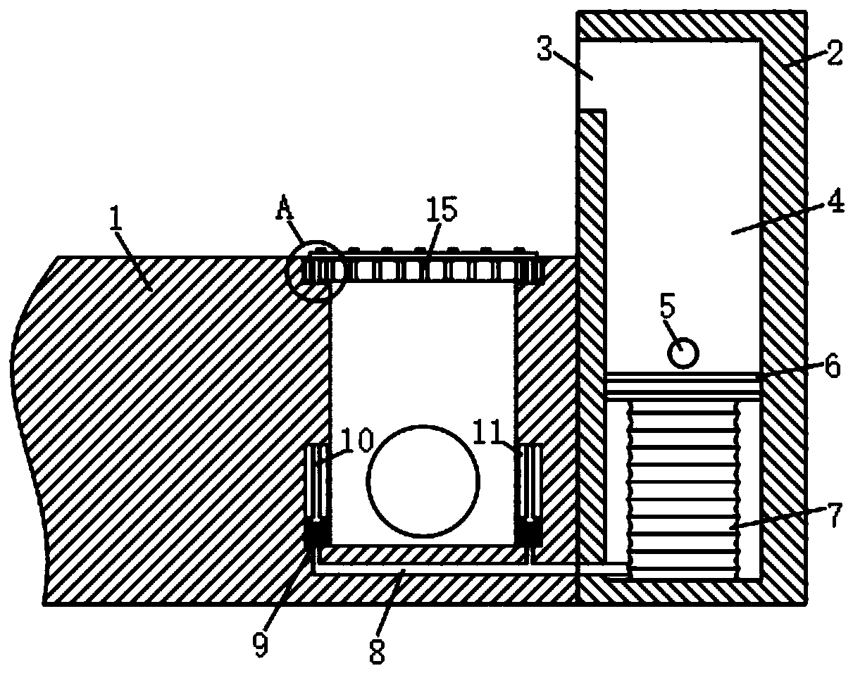
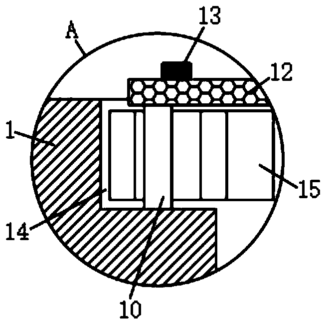
[0021] refer to Figure 1-3 , a kind of spongy city pavement drainage manhole cover clearing device, comprises pavement 1 and curb 2, and the side of pavement 1 close to curb 2 is provided with drainage channel, and the crossing of drainage channel is equipped with installation port 14, and installation port 14 is installed with Drainage well cover 15, curb 2 is provided with water inlet chamber 4, and the upper end side wall of curb 2 is provided with the water inlet 3 that communicates with water inlet chamber 4, is provided with big piston 6 in the water inlet chamber 4, and the big piston 6 An elastic air bag 7 is connected between the lower end and the inner bottom of the water inlet chamber 4, and the inner wall of the water inlet chamber 4 is provided with a drain pipe 5 communicating with the drain. The inner bottom of the folding airbag 9 is bonded with a vertically arranged folding airbag 9, and the folding airbag 9 communicates with the elastic airbag 7 through a tr...

Embodiment 2

[0024] refer to Figure 4-6 The difference between this embodiment and Embodiment 1 is that the inner top of the water inlet chamber 4 is fixedly connected with a vertically arranged fixed rod 18, and the fixed rod 18 is provided with a device cavity 16, and the upper and lower inner walls of the device cavity 16 are vertically connected. The threaded sleeve 27 is connected to straight rotation, and the upper end of the large piston 6 is fixedly connected with a pull rod 24. The upper end of the pull rod 24 extends into the threaded sleeve 27 and is fixedly connected with a threaded block 17. The threaded block 17 engages with the inner wall of the threaded sleeve 27. The outer wall of the threaded sleeve 27 is fixedly connected with the first bevel gear 26, the inner wall of the device chamber 16 is rotatably connected with the rotating rod 23, and one end of the rotating rod 23 is fixedly connected with the second bevel gear 25 meshing with the first bevel gear 26, The other...


PUM


Abstract

The invention discloses a device for cleaning blocking of a drainage well cover of a sponge city pavement. The device comprises the pavement and a curbstone, a drainage channel is formed in the side,close to the curbstone, of the pavement, a mounting opening is formed in the channel opening of the drainage channel, the drainage well cover is arranged in the mounting opening, a water inlet cavityis formed in the curbstone, a water inlet communicating with the water inlet cavity is formed in the side wall of the upper end of the curbstone, a big piston is arranged in the water inlet cavity, anelastic airbag is connected between the lower end of the big piston and the inner bottom of the water inlet cavity, a drainage pipe communicating with the drainage channel is arranged on the inner wall of the water inlet cavity, strip-shaped cavities are formed in both sides of the drainage channel, the inner bottoms of the strip-shaped cavities are bonded to a vertically arranged folding airbag,and the folding airbag communicates with the elastic airbag through an air pipe. The device for cleaning blocking of the drainage well cover of the sponge city pavement is reasonable in structure, and when water on the pavement where the drainage well cover is blocked is accumulated to a certain degree, debris clogged on the drainage well cover can be jacked up in time to clear the blockage in time.

Description

technical field [0001] The invention relates to the technical field of sponge city drainage, in particular to a device for removing blockage of a drainage manhole cover on a road surface of a sponge city. Background technique [0002] Sponge city is a new generation of urban stormwater management concept. It refers to the city's good "elasticity" in adapting to environmental changes and responding to natural disasters caused by rainwater. It can also be called "water elastic city". [0003] At present, in urban roads, in the event of heavy rainfall, water often occurs on the road surface, causing serious waterlogging. Most of the waterlogging is caused by the blockage of the drainage manhole cover on the road surface, which makes the waterlogging higher and higher. At present The way to clear the blockage generally needs to be cleaned manually, which is more troublesome, and it is impossible to clear the blockage in time. Contents of the invention [0004] The purpose of ...

Claims


Application Information

Patent Timeline
IPC IPC(8): E03F5/06E03F7/00
CPCE03F5/06E03F7/00
Inventor 台晨茜
Owner 山东格式医疗器械有限公司
Why Eureka
Try Eureka