Shield tunneling machine having robot tool changing function

A technology of robots and shield machines, applied in mining equipment, earthwork drilling, tunnels, etc., can solve problems such as difficult tool changes of shield machines, improve tool change efficiency and operational safety factor, and make tool change procedures simple and orderly , the effect of ingenious structural design

Active Publication Date: 2019-12-31
CHINA RAILWAY ENGINEERING EQUIPMENT GROUP CO LTD
View PDF8 Cites 2 Cited by
  • Summary
  • Abstract
  • Description
  • Claims
  • Application Information

AI Technical Summary

Problems solved by technology

[0004] Aiming at the deficiencies in the above-mentioned background technology, the present invention proposes a shield mach

Method used


Image

  • Shield tunneling machine having robot tool changing function
  • Shield tunneling machine having robot tool changing function
  • Shield tunneling machine having robot tool changing function

Examples


Embodiment 2

[0047] Example 2, such as Figure 4 As shown, a shield machine with robot tool changing function, the end effector 6-1 includes a movement adjustment mechanism 6-1-5, and the movement adjustment mechanism 6-1-5 is provided with a jaw assembly 6-1 -1. Image collection mechanism 6-1-2, bolt tightening mechanism 6-1-4 and high-pressure cleaning mechanism 6-1-3. The image collection mechanism is used to collect images when the end actuator performs actions, which is convenient for visual detection. The bolt tightening mechanism is used for screwing the bolts for installing the cutter; the high-pressure cleaning mechanism 3 is used for cleaning the cutter to be replaced. The jaw assembly 6-1-1, the image acquisition mechanism 6-1-2, the bolt tightening mechanism 6-1-4 and the high pressure cleaning mechanism 6-1-3 are located on the same board surface of the motion adjustment mechanism 6-1-5. The five parts are used together to realize efficient and safe replacement of knives.

...

Embodiment 3

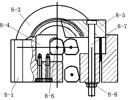
[0053] Example 3, such as Figure 7 As shown, an end effector based on a tool changing robot, the jaw assembly 6-1-1 includes a fixed jaw 101 and a moving jaw 102, the moving jaw 102 is hinged to the fixed jaw 101 and is opened and closed by a clamping cylinder 108 , that is, under the expansion and contraction of the clamping cylinder, the moving claw moves relative to the fixed claw to realize whether the tool is grasped or not. The top of the fixed claw 101 is connected with the sliding drive mechanism. Under the action of the sliding drive mechanism, the fixed claw and the movable claw can slide and translate to realize the change of their positions, so as to adapt to the disassembly and replacement of tools in different positions.

[0054] Further, the sliding drive mechanism includes a guide rail 105, the guide rail 105 is fixed in the connecting box 502, a slider 103 is slid on the guide rail 105, the slider 103 is fixedly connected with the fixed claw 101, and the sli...

Embodiment 4

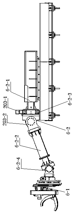
[0057] Example 4, such as Figure 8 As shown, an end effector based on a tool changing robot, the image acquisition mechanism 6-1-2 includes a camera 201 and a multi-degree-of-freedom adjustment platform 202, and the multi-degree-of-freedom adjustment platform 202 is located in the connecting box 502 and extends upward Connect the side of the box body 502 corresponding to the jaw assembly. The camera 201 is arranged on the upper part of the multi-degree-of-freedom adjustment platform 202 through the second rotation mechanism 203. The degree of freedom adjustment platform can drive the camera to swing and lift, and the rotation mechanism drives the camera to rotate, and cooperate with it to realize the adjustment of its own position and angle. The multi-degree-of-freedom adjustment platform 202 includes a fixed platform 2-1 and a moving platform 2-2, a swing lifting mechanism is arranged between the fixed platform 2-1 and the moving platform 2-2, and the swing lifting mechanism...


PUM


Abstract

The invention discloses a shield tunneling machine having a robot tool changing function. The shield tunneling machine having the robot tool changing function solves the problem that a shield tunneling machine difficultly changes tools in the prior art. The shield tunneling machine having the robot tool changing function comprises a tool disc, a main machine and a rear accessory sleeve, wherein asoil bin is arranged between the main machine and the tool disc, a robot bin and a tool magazine are arranged at the top of the interior of the main machine, the tool magazine is located in the robotbin, the robot bin is located at the rear of the soil bin, a tool changing gate is arranged on the bin wall of the soil bin, a tool changing robot is arranged in the robot bin, and novel tools suitable for tool changing of the tool changing robot are arranged on the tool disc. According to the shield tunneling machine having the robot tool changing function, the robot is used for the tool changing, the tool changing robot can move in the robot bin for the tool changing, the tool changing procedure is concise and orderly, a tail end executing mechanism of the tool changing robot realizes the purposes of performing clamping hoisting for the tools, loosening and tightening bolts, preforming high pressure cleaning for the tools, and meanwhile preforming image acquisition through a moving adjustment mechanism, a bolt loosening and tightening mechanism, a high pressure cleaning mechanism and an image acquisition mechanism, performs real-time monitoring, and improves tool changing efficiencyand operation safety coefficient.

Description

technical field [0001] The invention relates to the technical field of shield machines, in particular to a shield machine with a robot tool changing function. Background technique [0002] During the construction process of the full-face tunnel boring machine, the tool consumption is large and the replacement is frequent. The time for tool inspection and tool replacement accounts for more than 10% of the tunnel construction cycle. The existing tool inspection and tool replacement work mainly depends on manual work. Under the construction environment such as high pressure, there are great potential safety hazards in operation, and major safety accidents such as casualties are prone to occur. According to statistics, nearly 70% of tunnel construction safety accidents in China are directly related to manual tool change operations. The international industry problem of "difficult detection and dangerous tool change" has become a bottleneck restricting the safety and efficiency o...

Claims


Application Information

Patent Timeline
IPC IPC(8): E21D9/08
CPCE21D9/08
Inventor 叶蕾姜礼杰文勇亮杨航原晓伟赵梦媛欧阳凯
Owner CHINA RAILWAY ENGINEERING EQUIPMENT GROUP CO LTD
Why Eureka
Try Eureka