Axial multi-stage pressure reduction sleeve and multi-stage pressure reduction valve containing same

A pressure-reducing valve and sleeve technology, applied in the direction of sliding valves, valve details, valve devices, etc., can solve the problems of bulky valves, increased valve cavity volume, and increased risk of valve clogging, achieving compact structure, improved adjustment accuracy, Significant effect of blood pressure reduction ability

Active Publication Date: 2020-01-03
CHINA SHIP SCIENTIFIC RESEARCH CENTER (THE 702 INSTITUTE OF CHINA SHIPBUILDING INDUSTRY CORPORATION)
View PDF4 Cites 0 Cited by
  • Summary
  • Abstract
  • Description
  • Claims
  • Application Information

AI Technical Summary

Problems solved by technology

In the prior art, the structure of the multi-stage decompression valve sleeve is that several coaxial sleeves are arranged outside the valve core, and multiple holes are arranged on a single sleeve, and multi-layer sleeves are superimposed to perform multi-stage decompression; this technology The disadvantages are: the sleeve is a radial stacking structure. When the pressure difference of the valve is very large, it is necessary to stack multiple sleeves, which will increase the volume of the valve cavity and make the valve too heavy; in the case of a limited number of sleeves, In order to enhance the pressure-reducing capability of each stage of the sleeve, the diameter of the flow hole is usually set relatively small, which greatly increases the risk of valve blockage

Method used


Image

  • Axial multi-stage pressure reduction sleeve and multi-stage pressure reduction valve containing same
  • Axial multi-stage pressure reduction sleeve and multi-stage pressure reduction valve containing same
  • Axial multi-stage pressure reduction sleeve and multi-stage pressure reduction valve containing same

Examples


Embodiment Construction

[0030] The specific implementation manner of the present invention will be described below in conjunction with the accompanying drawings.

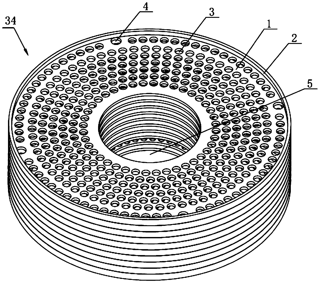
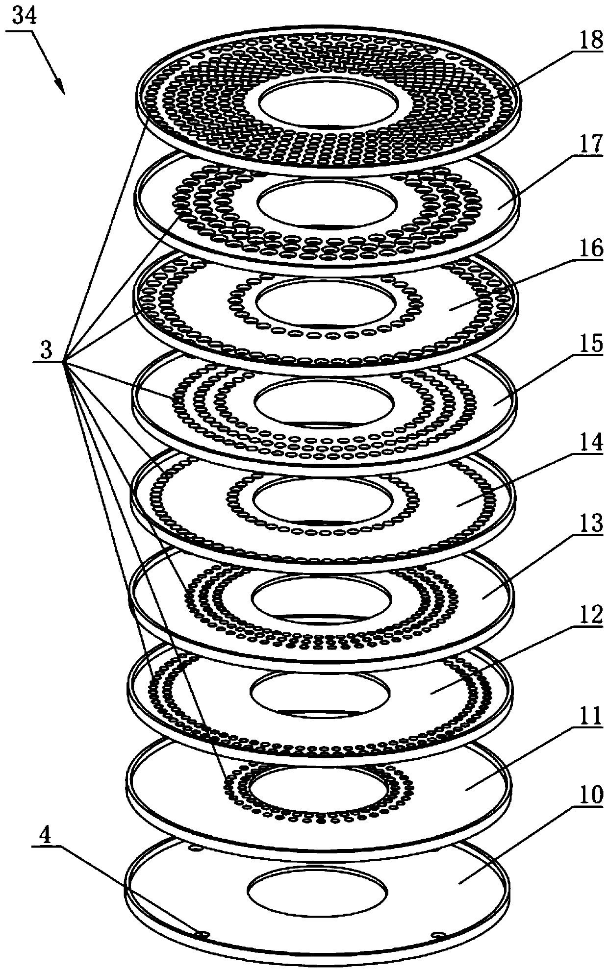
[0031] Such as figure 1 with figure 2 As shown, the axial multi-stage pressure-reducing sleeve of this embodiment includes multi-layer disks 1 spaced along the axial direction, and the space between adjacent disks 1 forms an interlayer flow channel; A plurality of through holes 3 are opened, and the plurality of through holes 3 are evenly distributed on the disc 1 with the center of the disc 1 as the center; the through holes 3 on adjacent discs 1 are distributed in a staggered manner along the radial direction of the disc 1 so that the fluid flows in the The circuitous flow in each interlayer channel.

[0032] Through the multi-layer disk 1 structure stacked axially, and through holes 3 are staggered on the adjacent disk 1 along its radial direction, the fluid flows in a circuitous way in each interlayer flow channel of the sleeve, and...


PUM


Abstract

The invention relates to an axial multi-stage pressure reduction sleeve and a multi-stage pressure reduction valve containing the same. The sleeve comprises a plurality of layers of disc sheets whichare arranged at intervals in the axial direction, wherein a plurality of through holes are uniformly distributed in each disc sheet by taking the center as a circle center; and the through holes in the adjacent disc sheets are distributed in a staggered manner in the radial direction, and the total area of the through holes in each disc sheet is progressively increased in sequence. The pressure reduction valve comprises a hollow valve body, wherein the sleeve is installed on the inner bottom surface of the valve body, a valve element is installed in a valve element hole in the middle part of the sleeve, and the valve element moves in the axial direction of the sleeve under the driving of a valve rod, and the bottom of the valve element is level with one layer of the disc sheets on the sleeve; and a fluid enters from an inlet, flows in a detouring manner via the through holes in the disc sheets and interlayer flow channels among the disc sheets, and then flows into the valve body and flows out, the fluid forms friction with the disc sheets during the detouring flowing, and then energy is lost, so that pressure loss is caused, and pressure reduction is realized. The pressure adjustment valve is ingenious in structure, small in size, capable of adjusting a pressure reduction coefficient through the position of the valve element, high in accuracy, long in service life, and low in cost.

Description

technical field [0001] The invention relates to the technical field of valves, in particular to an axial multi-stage decompression sleeve and a multi-stage decompression valve containing the sleeve. Background technique [0002] Regulating valves are often used to regulate the flow of media in pipelines. [0003] The flow path of the regulating valve generally adopts a high-inlet and low-outlet structure. The lower end of the valve core is made with a sealing surface that cooperates with the valve seat. The position of the valve core is controlled by the transmission mechanism, thereby controlling the flow of the medium through the valve to achieve flow regulation. The main problem of this structure is that when the pressure difference between the front and back of the valve is large, the flow rate of the medium in the valve is very high under the condition of small opening, and the medium has a strong scouring effect on the sealing surface of the valve core. Cavitation is ...

Claims


Application Information

Patent Timeline
Patent Type & Authority Applications(China)
IPC IPC(8): F16K3/02F16K3/30F16K47/08
CPCF16K3/0218F16K3/30F16K47/08
Inventor 梁赟何涛郝夏影
Owner CHINA SHIP SCIENTIFIC RESEARCH CENTER (THE 702 INSTITUTE OF CHINA SHIPBUILDING INDUSTRY CORPORATION)
Why Eureka
Try Eureka