
Small laser engraving machine for cubic column wood block

A technology of laser engraving machine and cubic column, which is applied in laser welding equipment, welding equipment, metal processing equipment and other directions, can solve problems such as workpiece processing that cannot be cubic column shape, and achieve good engraving effect, good fixing effect, engraving efficiency and high efficiency. The effect of quality improvement

Active Publication Date: 2020-01-07
SUZHOU MIKE LASER TECH SERVICE CO LTD
View PDF19 Cites 1 Cited by
  • Summary
  • Abstract
  • Description
  • Claims
  • Application Information

AI Technical Summary

Problems solved by technology

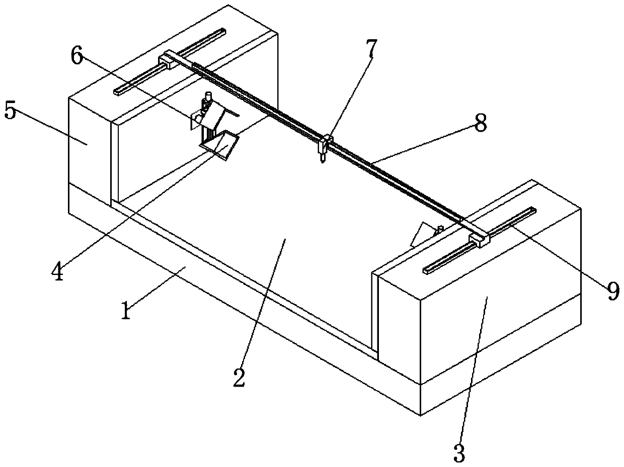
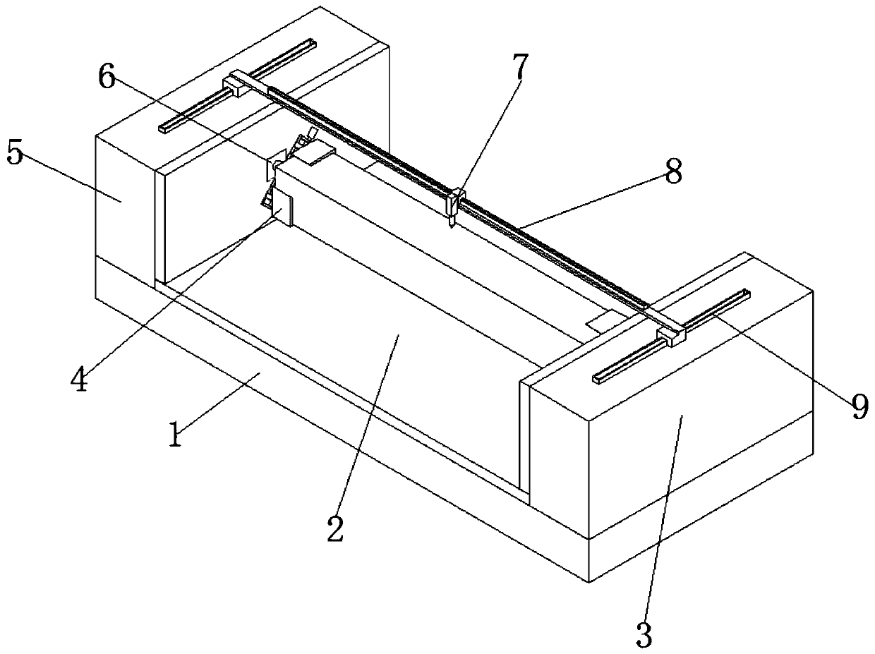
[0007] Aiming at the deficiencies of the prior art, the present invention provides a small laser engraving machine for cubic column blocks that can well carve cubic workpieces, which solves the problem that the existing laser engraving machines cannot process well the cubic column-shaped workpieces. The problem

Method used


Image

  • Small laser engraving machine for cubic column wood block
  • Small laser engraving machine for cubic column wood block
  • Small laser engraving machine for cubic column wood block

Examples


Embodiment Construction

[0032] The following will clearly and completely describe the technical solutions in the embodiments of the present invention with reference to the drawings in the embodiments of the present invention.

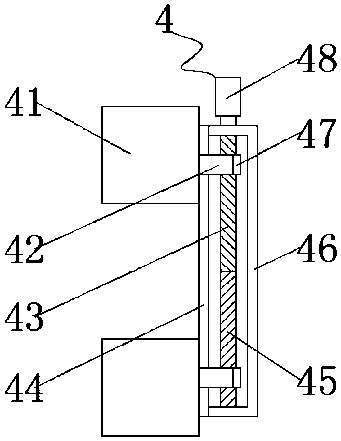
[0033] Embodiments of the present invention provide a small laser engraving machine for cubic column blocks, such as Figure 1-11 As shown, it includes a base 1, an operating table 2 fixedly connected to the top of the base 1, a first casing 5 fixedly connected to one side of the operating table 2, a second casing 3 fixedly connected to the other side of the operating table 2, a fixed The Y-guiding rail 9 connected to the top of the first casing 5 and the second casing 3, the X-guiding rail 8 slidingly fitted on the Y-guiding rail 9, the laser head 7 slidingly fitting on the X-guiding rail 8, the first machine Between the shell 5 and the second casing 3, two clamping mechanisms 4 for clamping the cube block are symmetrically arranged, and the clamping mechanism 4 includes two ...


PUM


Abstract

The invention provides a small laser engraving machine for a cubic column wood block and relates to the field of laser equipment. The small laser engraving machine comprises a base, an operation tablefixedly connected to the top of the base, a first case fixedly connected to one side of the operation table, a second case fixedly connected to the other side of the operation table, a Y-direction guide rail fixedly connected to the top of the first case and the top of the second case, an X-direction guide rail in sliding fit with the Y-direction guide rail, and a laser head in sliding fit with the X-direction guide rail. According to the small laser engraving machine for the cubic column wood block, when a workpiece in a cubic column shape is machined, at first, the workpiece in the cubic column shape is arranged between two clamping mechanisms, then an electric pushing rod is started, the electric pushing rod extends to enable the position of one clamping mechanism to get close to the other clamping mechanism, thus the distance between the two clamping assemblies is matched with the workpiece in the cubic column shape, then rotating handles on the two clamping mechanisms are rotated, and the rotating handles drive a first screw rod and a second screw rod to rotate synchronously.

Description

technical field [0001] The invention relates to the technical field of laser equipment, in particular to a small laser engraving machine for cubic column wood blocks. Background technique [0002] Laser engraving machine, as the name suggests, is an advanced equipment that uses laser to engrave the material that needs to be engraved. Laser engraving machines are different from mechanical engraving machines and other traditional manual engraving methods. Mechanical engraving machines use mechanical means, such as diamonds and other extremely hard materials to engrave other things. [0003] The laser engraving machine uses the thermal energy of the laser to engrave the material, and the laser in the laser engraving machine is its core. Generally speaking, laser engraving machines are used in a wider range, with higher engraving precision and faster engraving speed. Moreover, compared with the traditional hand-carving method, laser engraving can also achieve a very delicate e...

Claims


Application Information

Patent Timeline
Patent Type & Authority Applications(China)
IPC IPC(8): B23K26/02B23K26/362
CPCB23K26/02B23K26/362
Inventor 熊春霞
Owner SUZHOU MIKE LASER TECH SERVICE CO LTD
Learn More