Full-automatic gang drilling device

A fully automatic drilling device technology, which is applied in woodworking safety devices, fixed drilling machines, wood processing equipment, etc., can solve the problems of subjective judgment error, inability to stop the conveyor belt in the work area, and high safety risk of manual operation, so as to reduce the The effect of friction loss

Pending Publication Date: 2020-01-07
安徽信诺家具有限公司
View PDF8 Cites 3 Cited by
  • Summary
  • Abstract
  • Description
  • Claims
  • Application Information

AI Technical Summary

Problems solved by technology

[0003] If the drilling operation is performed manually: first, the efficiency is relatively low, and the speed can only reach 13 pieces per minute in general; second, the accuracy of manual operation will vary from person to person, and there is a large deviation; third , the safety risk of manual operation is high
If a drilling device with a row of drills at the lower end is used, it is difficult to satisfy the situation of drilling in multiple directions at the same time, such as the upper part, the lower part, and the left and right sides.
In the process of putting the plate on the conveyor belt for the general drilling device, the contact surface will be scratched due to the slidi

Method used


Image

  • Full-automatic gang drilling device
  • Full-automatic gang drilling device
  • Full-automatic gang drilling device

Examples


Embodiment 1

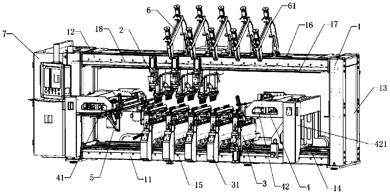
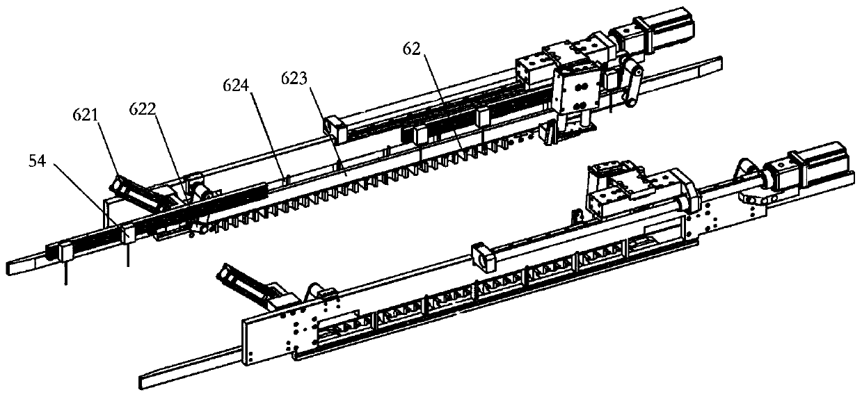
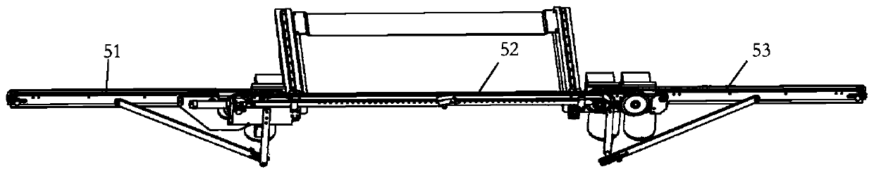
[0027] Such as Figure 1-6 As shown, a fully automatic drilling device includes a frame 1, a top drilling device 2, a bottom drilling device 3, a side drilling device 4, a conveying device 5, a positioning and fixing device 6, and a power supply device 7. The top drilling device 2, the bottom drilling device 3, the side drilling device 4, the positioning and fixing device 6, the conveying device 5 and the power supply device 7 are arranged in the frame 1.

[0028] The frame 1 is a rectangular parallelepiped frame as a whole, and the frame 1 includes a base 11, a cross beam 12 and a side column 13. The base 11 is a rectangular frame. There are four side posts 13 in total, and the four side posts 13 are respectively arranged at the four vertices of the base 11, and the side posts 13 are connected to the short bottom side of the base 11. The bottom of the side column 13 is provided with a foot, which can adjust the height of the corresponding side column 13 to adapt to uneven grou...


PUM


Abstract

A full-automatic gang drilling device is characterized by includes a rack, a top drilling device, a bottom drilling device, a side drilling device, a positioning and fixing device, a transmission device, and a power supply device, wherein the top drilling device, the bottom drilling device, the side drilling device, the positioning and fixing device, the transmission device and the power supply device are arranged at the rack; the transmission device includes a first section power conveyor belt, a second section power conveyor belt and a third section power conveyor belt; the positioning andfixing device includes an overturned pressing device, a clamping device and a positioning device. The overturned pressing device is arranged to effectively guarantee the adjustment of the top drillingdevice, and hindering is not caused by the movement of the top drilling device and the overturned pressing device; besides, hems are arranged on the upper surface of the support plate, and a scratch-proof strip is arranged on the mounting plate, and frictional loss of the plate during transmission of a conveyor belt is reduced.

Description

Technical field [0001] The invention relates to a plate drilling structure, in particular to a fully automatic drilling device. Background technique [0002] At present, most of the drilling equipment used in the production of wooden furniture is manually operated for drilling, or there is only a drilling device with a lower row of drills. [0003] If you use manual drilling operations: first, the efficiency is relatively low, and generally only can reach a speed of 13 blocks / min; second, the accuracy of manual operations will vary from person to person, and there will be large deviations; third , The safety risk of manual operation is higher. If a drilling device provided with a row of drills at the lower end is used, it is difficult to meet the situation of drilling in multiple directions at the same time, such as upper, lower, and left and right sides. Generally, when the plate is placed on the conveyor belt for transmission by the conventional row drilling device, since the e...

Claims


Application Information

Patent Timeline
IPC IPC(8): B27C3/04B27G21/00
CPCB27C3/04B27G21/00
Inventor 谢继明
Owner 安徽信诺家具有限公司
Why Eureka
Try Eureka