System and method for detecting dynamic RCS and frequency domain of unmanned aerial vehicle
A detection method and technology of unmanned aerial vehicles, applied in the field of radio detection, can solve the problems of undetectable dynamic RCS and frequency domain of unmanned aerial vehicles
- Summary
- Abstract
- Description
- Claims
- Application Information
AI Technical Summary
Problems solved by technology
Method used
Image

Examples
Embodiment 1
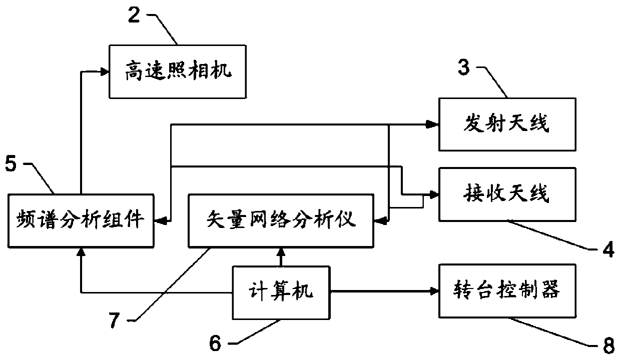
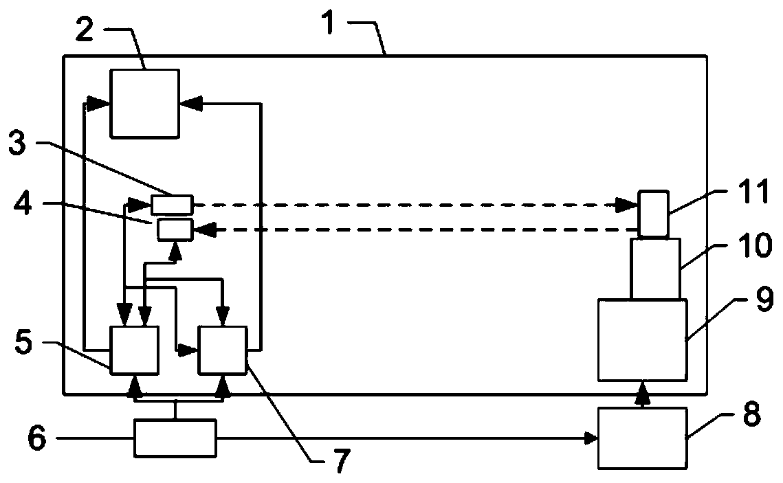
[0080] Such as Figure 1-2 As shown, a kind of unmanned aerial vehicle dynamic RCS and the detection system of frequency domain that the present embodiment provides, comprise: vector network analyzer 7, have at least one first channel module for transmitting signal, and have one for receiving signal The second channel module; the spectrum analysis component 5, which includes a signal source module and the receiver module; the turntable 9 component, including the turntable 9 and the turntable controller 8, the turntable 9 is used to carry the unmanned aerial vehicle, the The turntable controller 8 is used to step control the rotation of the turntable 9; the transmitting antenna 3 is connected to the first channel module and the signal source module respectively; the receiving antenna 4 is connected to the second channel module and the receiver module respectively High-speed camera 2, described high-speed camera 2 is connected with described vector network analyzer 7 signals, to...
Embodiment 2
[0088] Such as Figure 8 as shown, Figure 8This embodiment of the present invention provides a flowchart of a method for detecting UAV dynamic RCS based on the system described in Embodiment 1. The detection method of the dynamic RCS of the UAV is carried out in a microwave anechoic chamber. The detection method of this unmanned aerial vehicle dynamic RCS comprises steps:
[0089] S101. Place the unmanned aerial vehicle in a microwave anechoic chamber, and start the unmanned aerial vehicle to make its rotor rotate.
[0090] Specifically, the UAV is fixedly placed on the turntable, and can also be fixedly placed on the top of the bracket on the turntable. In this way, the position of the UAV is coordinated with the positions of the transmitting antenna, receiving antenna, high-speed camera, etc., and information exchange can be carried out more effectively. When the UAV's rotors are not activated, the UAV can be called a static UAV. After the drone is fixed, you can contr...
Embodiment 3
[0106] Such as Figure 9 As shown, on the basis of Embodiment 2, the embodiment of the present invention also provides another flow chart of a detection method for UAV dynamic RCS based on the system described in Embodiment 1; the detection method for UAV dynamic RCS also includes step:
[0107] S201. Setting the parameters of the vector network analyzer.
[0108] S202. Calibrate the vector network analyzer according to the parameters of the vector network analyzer.
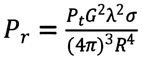
[0109] The parameter settings of the vector network analyzer must meet the microwave anechoic chamber conditions and the target RCS test requirements. Taking the Ku-band test as an example, the parameters of the vector network analyzer are set as follows: scanning range 12-18GHz, scanning bandwidth B=6Ghz, number of sampling points N, frequency resolution △f=B / N, time-domain dynamic range △t=1 / (△f), the maximum measurement distance in space L=(c*△t) / 2, the distance resolution, the vector network analyzer adop...
PUM
 Abstract
Description
Claims
Application Information
 - Generate Ideas
- Intellectual Property
- Life Sciences
- Materials
- Tech Scout
- Unparalleled Data Quality
- Higher Quality Content
- 60% Fewer Hallucinations
Browse by: Latest US Patents, China's latest patents, Technical Efficacy Thesaurus, Application Domain, Technology Topic, Popular Technical Reports.
© 2025 PatSnap. All rights reserved.Legal|Privacy policy|Modern Slavery Act Transparency Statement|Sitemap|About US| Contact US: help@patsnap.com