Heat destructive disconnecting switch and socket with such switch

A technology of thermal destruction and switching, which is applied to the components of flip switches/rocker switches, electric switches, thermal switches, etc., which can solve the problems of incomplete socket contact, incomplete insertion, and price rise, and achieve price improvement. Expensive, simple overall structure, and low manufacturing cost

Active Publication Date: 2020-01-10
易湘云
View PDF14 Cites 0 Cited by
  • Summary
  • Abstract
  • Description
  • Claims
  • Application Information

AI Technical Summary

Problems solved by technology

[0008] 1. The metal pins of the plug are severely oxidized, and the metal pins are covered with oxides. When the plug is inserted into the socket, the oxide with poor conductivity will increase the resistance and the socket will overheat.
[0009] 2. When the metal pin of the plug is inserted into the socket, the insertion is not complete, resulting in only partial contact, and the too small contact area causes the socket to overheat
[0010] 3. The metal pins of the plug are deformed or worn, resulting in incomplete contact when inserted into the socket, and too small contact area causes the socket to overheat
[0011] 4. The metal pins of the plug or the metal sheet of the socket are stained with foreign matter, such as dust or dirt, which makes the conductivity poor, so the resistance becomes larger and overheats
[0014] Since there are many situations that cause the socket to overheat, and the distance between the socket and the bimetal of the overload protection switch will cause a huge temperature difference, in order to effectively achieve overheat protection, an overload protection should be set on each socket of the extension cord socket. Protection switch, but the price of the bimetal type overload protection switch is relatively high. If it is installed on each socket of the extension cord socket, the price will rise sharply, which is not conducive to popularization.

Method used


Image

  • Heat destructive disconnecting switch and socket with such switch
  • Heat destructive disconnecting switch and socket with such switch
  • Heat destructive disconnecting switch and socket with such switch

Examples


Embodiment Construction

[0048] Based on the above technical features, the main functions of the socket of the present invention and its heat-damaged power-off switch can be clearly presented in the following embodiments.

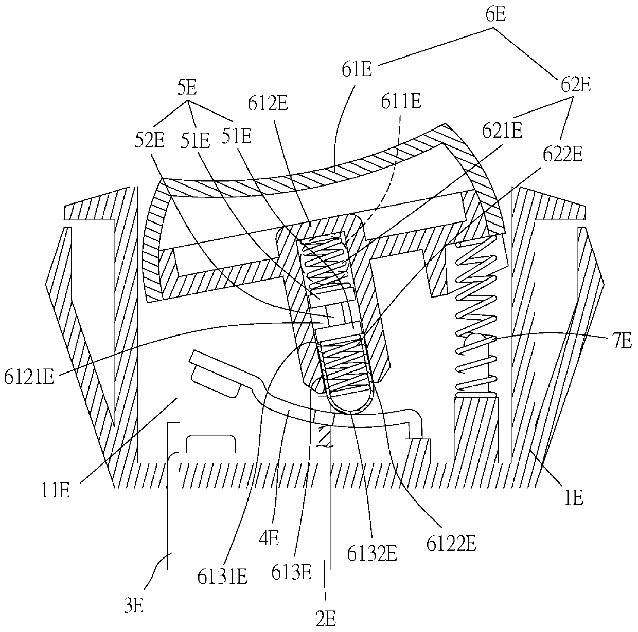
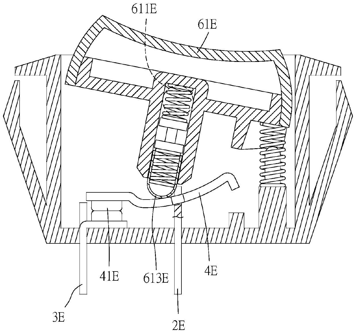
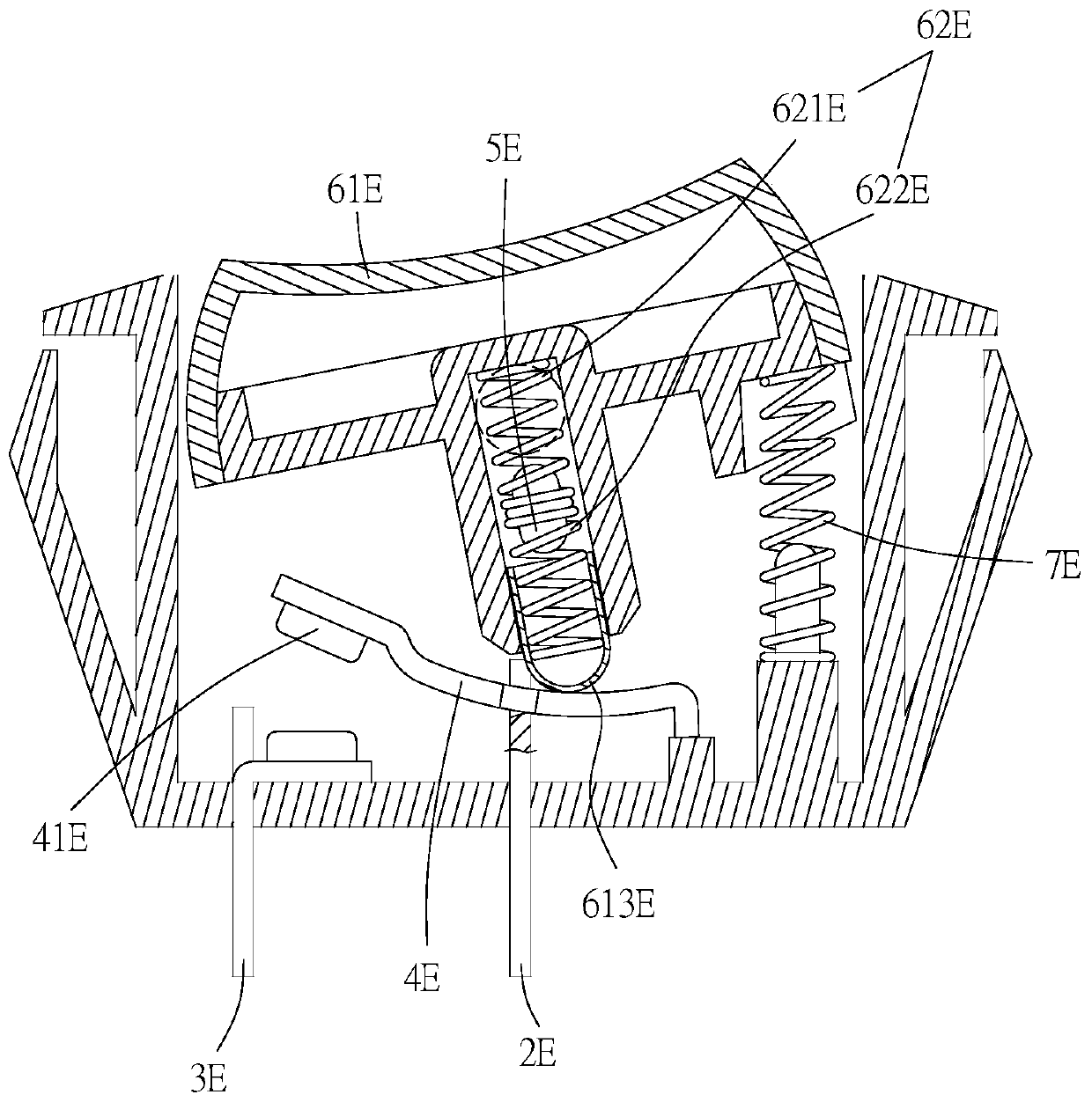
[0049] Please refer to the first embodiment of the present invention figure 1 As shown, this embodiment is a switch for thermal damage and power-off, and in this embodiment it is a rocker switch, and figure 1 Indicates that the rocker switch is off.

[0050] The rocker switch includes:

[0051] The seat 1E has an accommodating space 11E. A first conductive element 2E and a second conductive element 3E are both passed through the base body 1E. A movable conductive part is arranged in the accommodating space 11E, the movable conductive part is a seesaw conductive part 4E, the seesaw conductive part 4E straddles the first conductive part 2E and is electrically connected to the first conductive part 2E . An overheating damage member 5E can be destroyed at a damage temperature rang...


PUM


Abstract

Disclosed are a heat destructive disconnecting switch and a socket with such a switch. The heat destructive disconnecting switch comprises a first conductive member, a second conductive member, a movable conductive member, an overheating destructive member, an operating component, and a second elastic member. The movable conductive member enables electrical conduction with the first conductive member and the second conductive member. A first elastic member having a first spring and a second spring which are compressed and provided with a first elastic force, and the second elastic member is provided with a second elastic force. When the overheating destructive member is destructed due to overheating, the first elastic force is diminished or vanished, which causes the second elastic force to be larger than the first elastic force and forces the movable conductive member to disconnect from current conducting state between the first conductive member and the second conductive member, thereby achieving a protective effect from overheating. The socket is a socket which includes such a heat destructive disconnecting switch.

Description

technical field [0001] The present invention relates to a thermal breakage power-off switch and a socket with the switch, in particular to a power-off structure different from fuses and bimetal strips. The overheating breaker of the present invention does not rely on current passing to perform Destruction, and the destruction is performed by heat energy transfer and the switch is de-energized, and a socket with the switch. Background technique [0002] The existing rocker switch is to control the switch to pivot reciprocally in a certain angle range to control the access and disconnection of the switch. For example, China Taiwan Patent No. 560690 "Spark shielding structure of switch", when the switch pivots, use Locating features position it in a first position or a second position to create a path or break. [0003] In the existing press switch, each press operation can repeatedly control the on-off and off-circuit of the switch. The button uses a reciprocating button stru...

Claims


Application Information

Patent Timeline
Patent Type & Authority Applications(China)
IPC IPC(8): H01H23/02H01H23/12H01R13/713
CPCH01H23/02H01H23/12H01R13/7137H01H23/105H01H23/205H01H37/764H01H89/04H01H13/20H01H13/28H01H13/56H01H37/32H01H2205/00H01R13/10H01R13/71
Inventor 易湘云
Owner 易湘云
Why Eureka
Try Eureka