Electrical equipment

An electrical equipment, electromagnetic coupling technology, applied in electrical components, lighting and heating equipment, circuits, etc., can solve problems such as limiting the number of electrical equipment, failure, and limited hinge hole size

Pending Publication Date: 2020-01-10
TYCO ELECTRONICS (SHANGHAI) CO LTD
View PDF0 Cites 1 Cited by
  • Summary
  • Abstract
  • Description
  • Claims
  • Application Information

AI Technical Summary

Problems solved by technology

However, due to the need to pass the wires through the hinge hole, this arrangement complicates the assembly process and disassembly process of the product; due to the limited size of the hinge hole, this arrangement makes the hinge hole unable to accommodate more wires, thereby limit

Method used


Image

  • Electrical equipment
  • Electrical equipment
  • Electrical equipment

Examples


no. 1 example

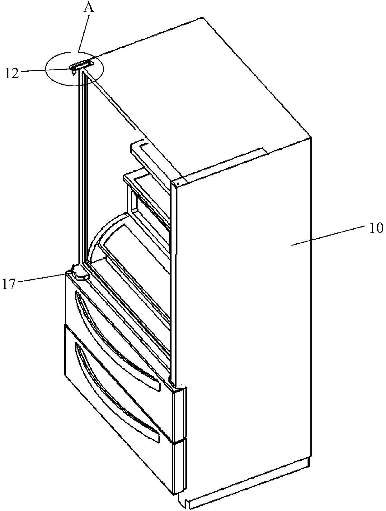
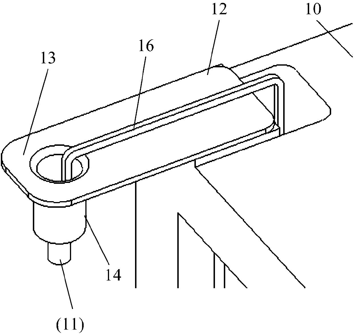
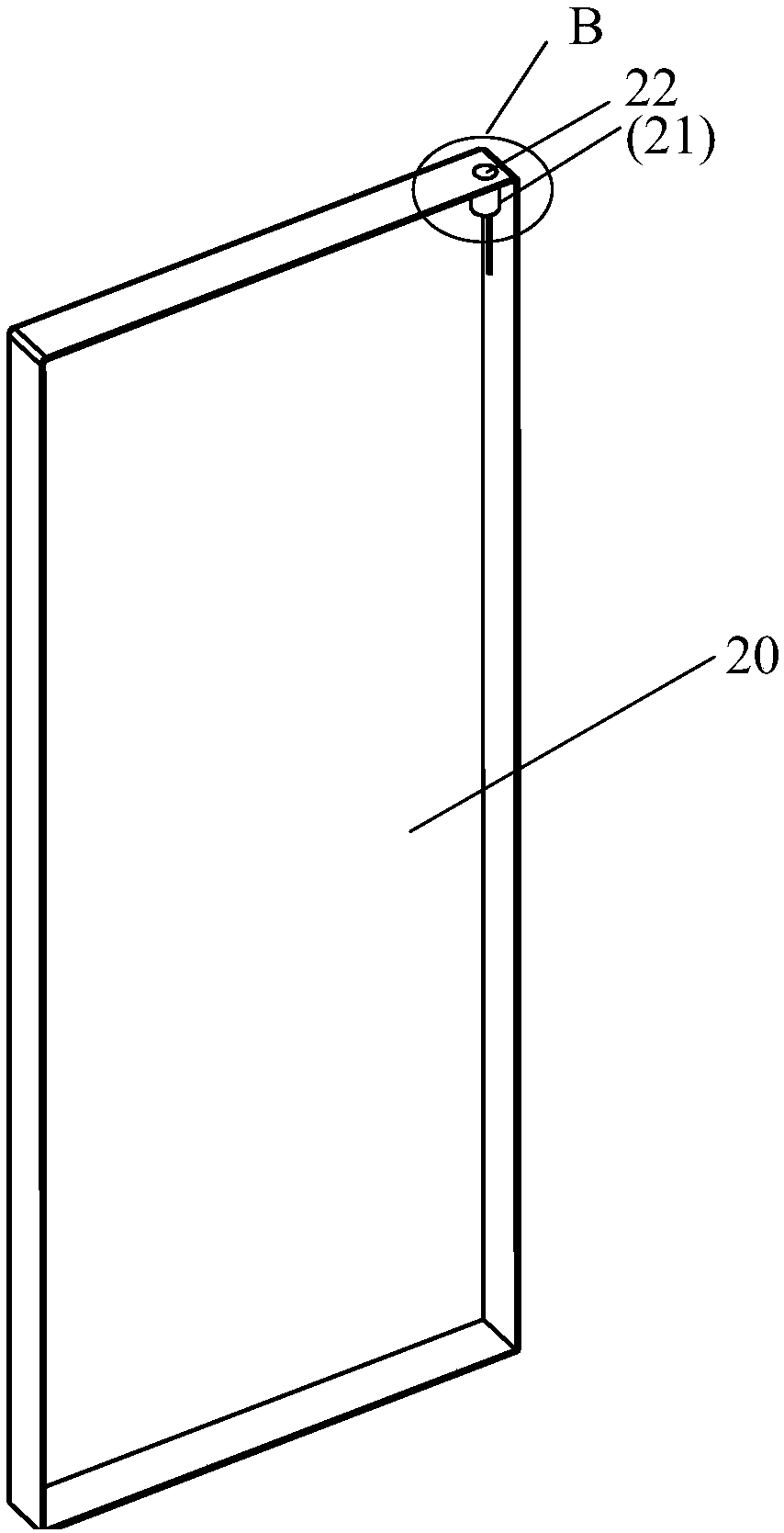
[0039] figure 1 is a schematic perspective view of the main body of the electrical device according to the first embodiment of the present invention; figure 2 for figure 1 Enlarged view of part A shown; image 3 is a schematic perspective view of a pivoting part of an electrical device according to a first embodiment of the present invention; and Figure 4 for image 3 Enlarged view of part B shown.

[0040] Such as Figure 1-4 As shown, in an exemplary embodiment of the present invention, an electrical device is provided, comprising: a main body 10; a pivoting member 20 to be pivotally connected to the main body 10; a first coil 11 mounted on the main body 10; and the second coil 21, installed on the pivot member 20; wherein, the first coil 11 passes through the second coil 21 at least partially to form an electromagnetic coupling between the first coil 11 and the second coil 21, thereby realizing Wireless power supply between the main body 10 and the pivot member 20 ....

no. 2 example

[0050] Figure 9 is a schematic perspective view of the main body of the electrical device according to the second embodiment of the present invention; Figure 10 for Figure 9 Enlarged view of part E shown; Figure 11 is a schematic perspective view of a pivoting part of an electrical device according to a second embodiment of the present invention; and Figure 12 for Figure 11 Enlarged view of section F shown.

[0051] Similar to the first embodiment, such as Figure 9-12 As shown, an electrical device is provided, including: a main body 110, a pivoting member 120, a first coil 111 and a second coil 121, wherein the first coil 111 at least partially passes through the second coil 121 so that the first coil Electromagnetic coupling is formed between 111 and the second coil 121 , so as to realize wireless power supply between the main body 110 and the pivoting member 120 .

[0052] Further, in an exemplary embodiment of the present invention, the electrical equipment is...


PUM


Abstract

The present invention discloses electrical equipment, which comprises a main body part, a riveting component, a first coil and a second coil, wherein the pivoting component is connected to the main body part in a pivoting manner; the first coil is mounted on the main body part; and the second coil mounted on the pivoting component; and at least part of the first coil penetrates through the secondcoil to form electromagnetic coupling between the first coil and the second coil, so that wireless power supply between the main body part and the pivoting component is realized.

Description

technical field [0001] Embodiments of the present invention relate to an electrical device, in particular to an electrical device capable of realizing wireless power supply between its components that pivot relative to each other. Background technique [0002] In electrical equipment, especially in household electrical equipment, two components with a relative pivotal movement relationship are generally connected by a pivot joint. Due to the need to communicate between components, such as the need to transmit power between components, wires need to pass through the hinge holes to transmit power from one end of the pivot to the other. However, due to the need to pass the wires through the hinge hole, this arrangement complicates the assembly process and disassembly process of the product; due to the limited size of the hinge hole, this arrangement makes the hinge hole unable to accommodate more wires, thereby limiting the use of The number of electrical devices; and, since t...

Claims


Application Information

Patent Timeline
IPC IPC(8): H02J50/10
CPCH02J50/10F25D2323/024F25D23/028D06F39/14D06F34/10H02J50/90H01F38/14
Inventor 钟元王晨希卞卫锋
Owner TYCO ELECTRONICS (SHANGHAI) CO LTD
Why Eureka
Try Eureka