
Deploying and controlling equipment

A device and a technology for controlling circuit boards, which are applied in the field of monitoring equipment and can solve the problems of inability to automatically identify valid information, poor shooting effects, and poor lighting effects.

Pending Publication Date: 2020-01-10
亮视智联(深圳)科技有限公司
View PDF0 Cites 1 Cited by
  • Summary
  • Abstract
  • Description
  • Claims
  • Application Information

AI Technical Summary

Problems solved by technology

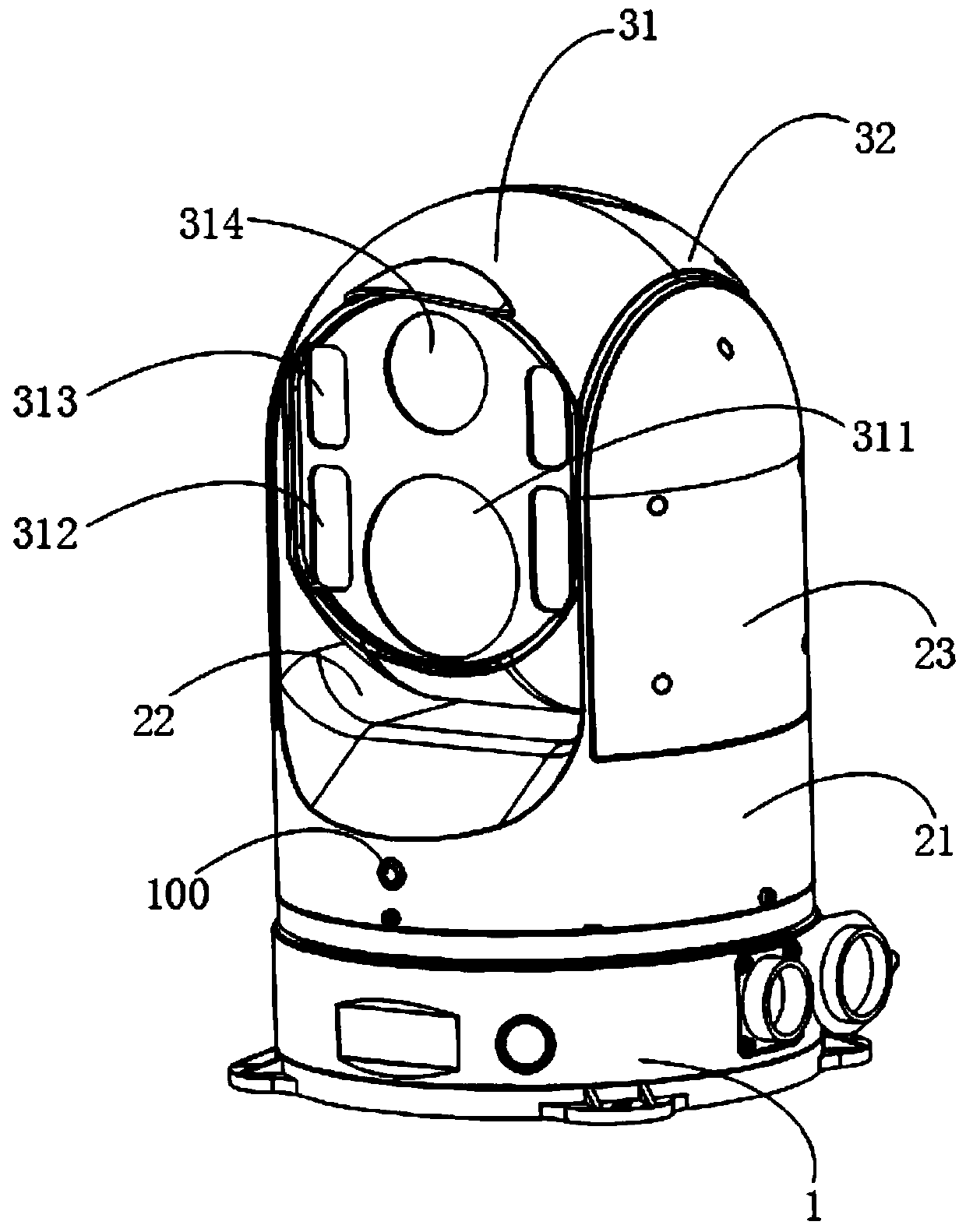
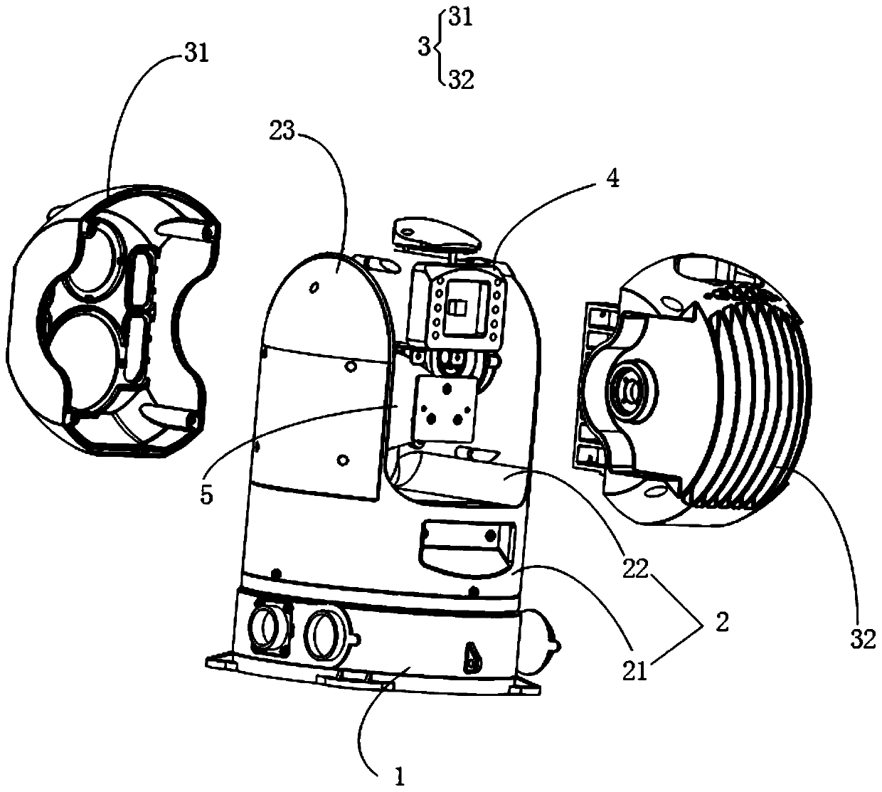
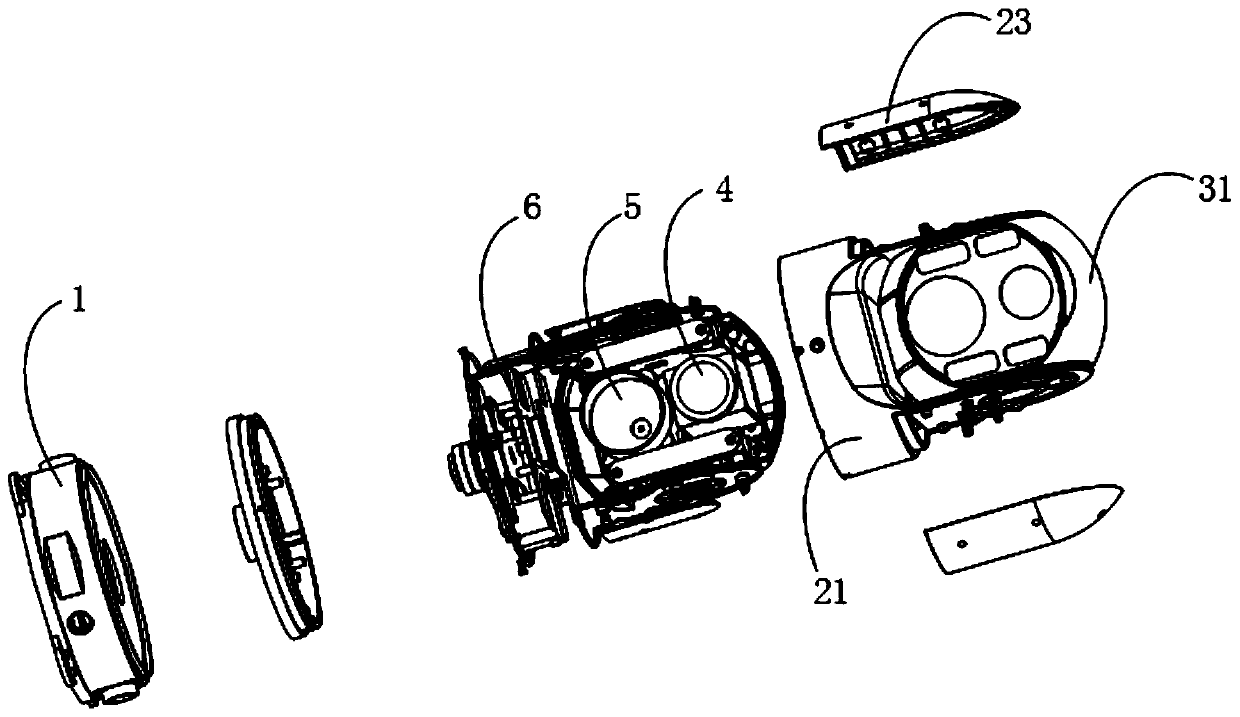
[0003] The main purpose of the present invention is to provide a control device, which solves the problem that the traditional control device has a poor light supplement effect at night, low temperature, rain and snow and other bad weather, resulting in poor shooting effect and unable to automatically identify effective information.

Method used


Image

  • Deploying and controlling equipment
  • Deploying and controlling equipment
  • Deploying and controlling equipment

Examples


Embodiment Construction

[0055] The technical solutions in the embodiments of the present invention will be clearly and completely described below in conjunction with the accompanying drawings in the embodiments of the present invention. Obviously, the described embodiments are only a part of the embodiments of the present invention, rather than all the embodiments. Based on the embodiments of the present invention, all other embodiments obtained by those of ordinary skill in the art without creative work shall fall within the protection scope of the present invention.

[0056] It should be noted that all the directional indications (such as up, down, left, right, front, back...) in the embodiments of the present invention are only used to explain the difference between components in a specific posture (as shown in the accompanying drawings). If the relative positional relationship, movement situation, etc. change, the directional indication will change accordingly.

[0057] In addition, the descriptions r...


PUM


Abstract

The invention provides a deploying and controlling equipment which comprises a base, a supporting base, a rotating shell, a camera shooting assembly, a lighting assembly and a control circuit board, the supporting base comprises a support and a rotating groove formed in the inner side of the support, and the support is rotationally connected with the base; the rotating shell is rotatably connectedwith the support, and the rotating shell is arranged in the rotating groove; the camera assembly is arranged in the rotating shell; the lighting assembly is connected into the rotating shell. The control circuit board is arranged in the support; the camera assembly is connected with the control circuit board; an identification module is integrated on the control circuit board; the identificationmodule is used for identifying image data shot by the camera assembly; therefore, the shooting sharpness of the camera shooting assembly is increased, the effective information of the image data shotby the camera shooting assembly can be automatically recognized in cooperation with the recognition module, and the human face and license plate information in the image data can be automatically recognized.

Description

Technical field [0001] The invention relates to the field of monitoring equipment, in particular to a deployment control equipment. Background technique [0002] Traditional deployment control equipment generally has a camera function to realize on-site shooting records, data return, real-time monitoring and command, etc. During the camera process, the deployment control equipment generally realizes night video monitoring through infrared supplementary light. The light supplement effect in severe weather such as snow is poor, resulting in poor shooting effect, and effective information cannot be automatically recognized. Summary of the invention [0003] The main purpose of the present invention is to provide a deployment control device, which solves the problem that the traditional deployment control device has poor light supplement effect at night, low temperature, rain and snow and other bad weather, resulting in poor shooting effect and unable to automatically identify effecti...

Claims


Application Information

Patent Timeline
IPC IPC(8): H04N7/18H04N5/225H04N5/232
CPCH04N7/18H04N23/56H04N23/50H04N23/57H04N23/55H04N23/695
Inventor 颜伦歆贺冬
Owner 亮视智联(深圳)科技有限公司
Learn More