Transformer structure

A technology of transformers and inductors, applied in the field of inductor structure, can solve problems such as coupling coefficient and quality factor reduction

Inactive Publication Date: 2020-01-14
徐州国力电力设备有限公司
View PDF0 Cites 0 Cited by
  • Summary
  • Abstract
  • Description
  • Claims
  • Application Information

AI Technical Summary

Problems solved by technology

However, achieving a satisfactorily higher inductance usually results in a lower coupling coefficient and quality factor

Method used


Image

  • Transformer structure
  • Transformer structure
  • Transformer structure

Examples


Embodiment Construction

[0011] Reference will now be made in detail to present embodiments of the present disclosure, examples of which are illustrated in the accompanying drawings. Wherever possible, the same reference numbers will be used throughout the drawings and the description to refer to the same or like parts.

[0012] The terms used in this specification generally have their ordinary meanings in the art and in the specific context where each term is used. The use of examples in this specification, including examples of any term discussed herein, is illustrative only and in no way limits the scope and meaning of the disclosure or any exemplified term. Also, the present disclosure is not limited to the various examples given in this specification.

[0013] As used herein, the terms "comprising", "including", "having" and the like are to be construed as open-ended, meaning including but not limited to.

[0014] Reference throughout this specification to "one embodiment" or "one embodiment" m...


PUM


Abstract

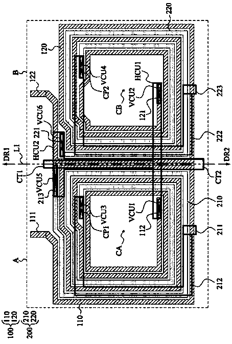
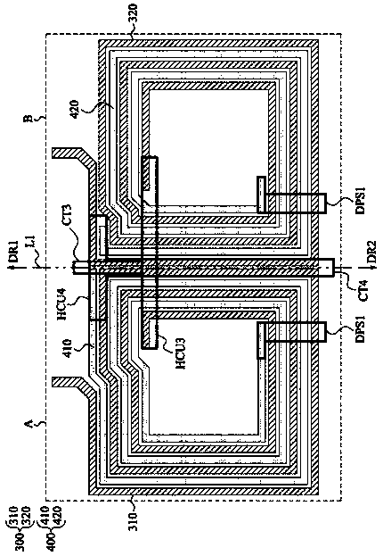
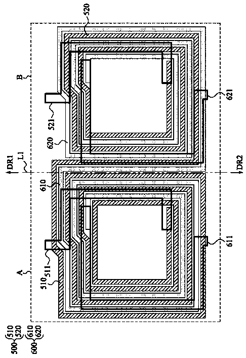
The invention discloses a transformer structure including a first inductor and a second inductor. The first inductor has a first turn and a second turn. The second inductor has a third turn and a fourth turn. The first turn of the first inductor and the third turn of the second inductor are disposed in a first region of a first metal layer. The second turn of the first inductor and the fourth turnof the second inductor are disposed in a second region of the first metal layer. The first region is adjacent to the second region.

Description

technical field [0001] The present disclosure relates to an inductor structure. More specifically, the present disclosure relates to a transformer structure. Background technique [0002] Today, inductor devices and transformer structures formed from inductors are essential in integrated circuits. However, achieving a satisfactorily higher inductance usually results in a lower coupling coefficient and quality factor. Therefore, improvements to these transformer structures are needed. Contents of the invention [0003] The present invention provides a transformer structure with a good quality factor (Q value). [0004] The present disclosure relates to a transformer structure. The transformer structure includes a first inductor and a second inductor. The first inductor has first and second turns. The second inductor has third and fourth turns. The first turn of the first inductor and the third turn of the second inductor are arranged mutually in the first region of t...

Claims


Application Information

Patent Timeline
IPC IPC(8): H01F27/28H01F27/30
CPCH01F27/2804H01F27/306H01F2027/2819
Inventor 张海峰
Owner 徐州国力电力设备有限公司
Why Eureka
Try Eureka