Bearing dismounting auxiliary device

An auxiliary device and bearing technology, which is applied in the field of metallurgy, can solve the problems of complex structure and difficult use of bearing spreaders

Inactive Publication Date: 2020-01-17
CHINA MCC20 GRP CORP
View PDF7 Cites 3 Cited by
  • Summary
  • Abstract
  • Description
  • Claims
  • Application Information

AI Technical Summary

Problems solved by technology

[0008] In view of this, the present invention proposes a bearing dismounting auxiliary device, which aims to solve the problem of complex structure and difficult use of the existing bearing spreader

Method used


Image

  • Bearing dismounting auxiliary device
  • Bearing dismounting auxiliary device
  • Bearing dismounting auxiliary device

Examples


Embodiment Construction

[0025] Exemplary embodiments of the present disclosure will be described in more detail below with reference to the accompanying drawings. Although exemplary embodiments of the present disclosure are shown in the drawings, it should be understood that the present disclosure may be embodied in various forms and should not be limited by the embodiments set forth herein. Rather, these embodiments are provided for more thorough understanding of the present disclosure and to fully convey the scope of the present disclosure to those skilled in the art. It should be noted that, in the case of no conflict, the embodiments of the present invention and the features in the embodiments can be combined with each other. The present invention will be described in detail below with reference to the accompanying drawings and examples.

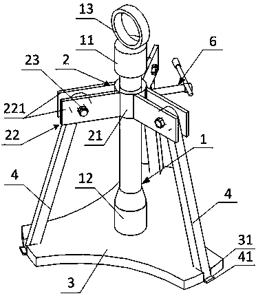
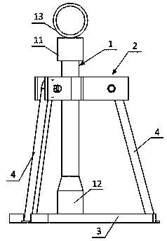
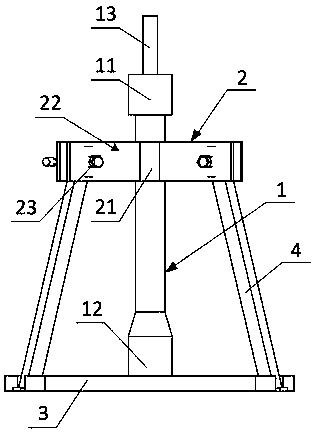
[0026] see Figure 1 to Figure 4 , which shows a preferred structure of the bearing dismounting auxiliary device provided by the embodiment of the present in...


PUM


Abstract

The invention provides a bearing dismounting auxiliary device. The bearing dismounting auxiliary device comprises a supporting rod, a clamp fixing mechanism and a clamp inner supporting plate, whereinthe clamp inner supporting plate is located below the clamp fixing mechanism and is arranged in parallel to the clamp fixing mechanism, at least three clamps are arranged on the clamp fixing mechanism, the first ends of the clamps are rotatably arranged on the clamp fixing mechanism, a spatial prism structure is formed by taking the clamps as side edges, a plurality of clamping structures are arranged in the circumferential direction of the clamp inner supporting plate and are in one-to-one correspondence with the clamps and used for clamping the corresponding clamps, the bottom end of the supporting rod is arranged on the top wall of the clamp inner supporting plate, the upper portion of the supporting rod is adjustably connected to the clamp fixing mechanism in the height direction position, the distance between the clamp inner supporting plate and the clamp fixing mechanism is adjusted, the positions where the clamps are connected to the clamp inner supporting plate are adjusted, the included angle between each clamp and the axis of the supporting rod is adjusted, an inner ring of a bearing abuts against the clamps, and the bearing is hoisted and dismounted.

Description

technical field [0001] The invention relates to the technical field of metallurgy, in particular to an auxiliary device for dismounting a bearing. Background technique [0002] Rolling technology is an important part of metallurgical technology, and the roll is an important part of the rolling mill, and the working conditions are the most complicated. The roll is mainly composed of three parts: the roll body, the roll neck and the shaft head. The roll body is the working part of the roll, and the roll neck is the part in contact with the bearing, which is connected with the transmission device by a joint. [0003] Roll bearings are important components used to support the roll and maintain its correct position in the machine frame. The roll bearing is an important part of the rolling mill. The quality of its assembly, adjustment and maintenance has a direct impact on the life of the bearing, the dimensional accuracy of the product, and the operating rate of the rolling mill...

Claims


Application Information

Patent Timeline
Patent Type & Authority Applications(China)
IPC IPC(8): B25B27/06
CPCB25B27/06
Inventor 于春亮刘猛谷媛媛
Owner CHINA MCC20 GRP CORP
Why Eureka
Try Eureka