Indoor unit for air conditioner
A technology for indoor units and air conditioners, applied in the field of indoor units, can solve problems such as uneven temperature, and achieve the effect of suppressing uneven temperature and improving comfort.
- Summary
- Abstract
- Description
- Claims
- Application Information
AI Technical Summary
Problems solved by technology
Method used
Image

Examples
Embodiment approach 1
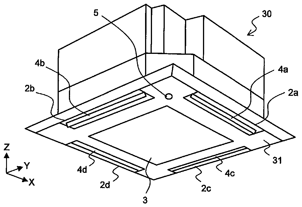
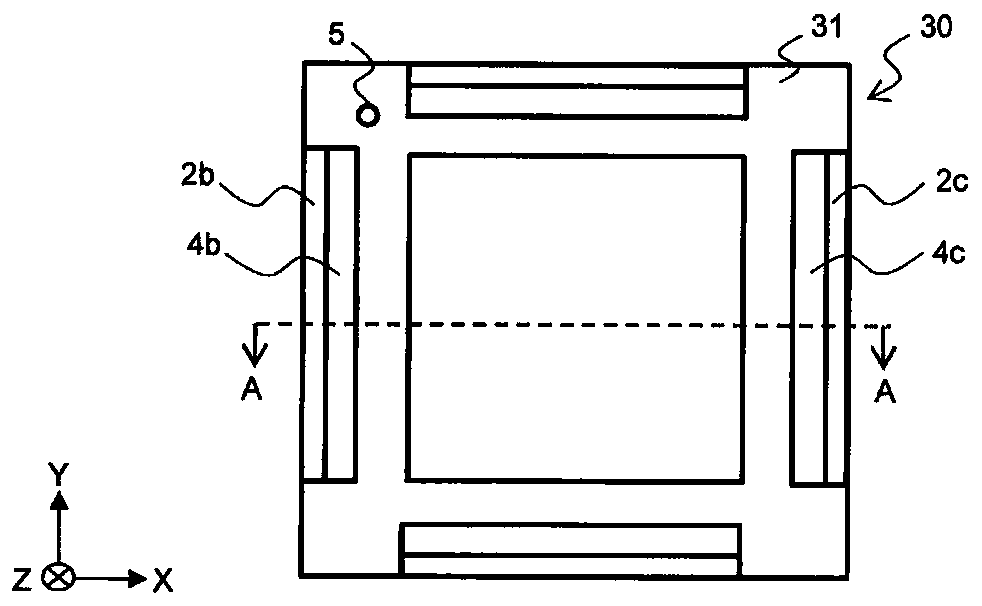
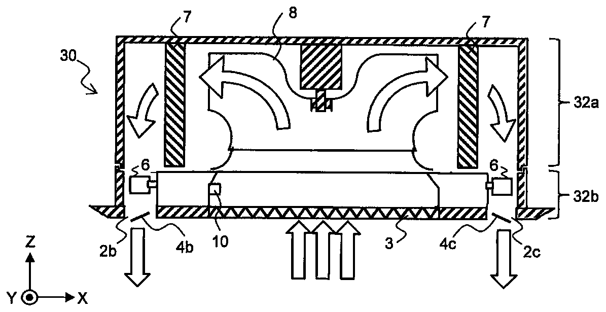
[0039] The configuration of the air conditioner according to Embodiment 1 will be described. figure 1 It is an external perspective view showing a configuration example of the indoor unit of the air conditioner in Embodiment 1 of the present invention. figure 2 is viewed from the lower surface side figure 1 The top view of the indoor unit shown. image 3 yes figure 2 The cross-sectional schematic diagram of the indoor unit at the dotted line AA shown.
[0040] In this Embodiment 1, figure 1 The illustrated indoor unit 30 is a four-way ceiling box indoor unit. The indoor unit 30 has a rectangular parallelepiped casing. The indoor unit 30 is embedded in the ceiling of a room to be air-conditioned. Such as figure 2 As shown, the lower surface 31 of the indoor unit 30 is rectangular, and the lower surface 31 is exposed from the ceiling toward the indoor side. A rectangular suction port 3 is provided at the center of the lower surface 31 of the indoor unit 30 . A grid-l...
Embodiment approach 2
[0073] The air conditioner according to Embodiment 1 eliminates temperature unevenness in the space to be air-conditioned and reduces the user's feeling of wind by cooperating the vertical air direction adjustment parts 4a to 4d with the plurality of left and right air direction adjustment parts 6 . The air conditioner according to Embodiment 2 provides an air-conditioning target space in which temperature unevenness is further reduced during heating operation.
[0074] The configuration of the air conditioner according to Embodiment 2 is the same as that of the air conditioner 1 described in Embodiment 1, and therefore description of the configuration will be omitted in Embodiment 2. FIG. During heating operation, the warm air exhausted from the indoor unit 30 of the air conditioner 1 tends to stay on the ceiling surface, resulting in hot head and cold feet. As an example of a method of preventing such a state, the operation of the air conditioner 1 according to Embodiment 2 ...
Embodiment approach 3
[0082] The air conditioners of Embodiments 1 and 2 reduce temperature unevenness in the air-conditioned space by interlocking the vertical air direction adjusters 4a to 4d with the plurality of lateral air direction adjusters 6, thereby improving user comfort. The air conditioner according to Embodiment 3 has a human body position detection unit which detects the position of a person in the air-conditioning target space, and controls to automatically blow air to the person. Since the body temperature varies depending on the person, Embodiment 3 is suitable for people who need to blow air from the air conditioner.
[0083] The configuration of the air conditioner according to Embodiment 3 will be described. In Embodiment 3, detailed descriptions of the same structures as Embodiments 1 and 2 are omitted, and points different from Embodiments 1 and 2 are described in detail.
[0084] Figure 13 It is a plan view when the indoor unit of the air conditioner in Embodiment 3 of thi...
PUM
 Abstract
Description
Claims
Application Information
 - R&D
- Intellectual Property
- Life Sciences
- Materials
- Tech Scout
- Unparalleled Data Quality
- Higher Quality Content
- 60% Fewer Hallucinations
Browse by: Latest US Patents, China's latest patents, Technical Efficacy Thesaurus, Application Domain, Technology Topic, Popular Technical Reports.
© 2025 PatSnap. All rights reserved.Legal|Privacy policy|Modern Slavery Act Transparency Statement|Sitemap|About US| Contact US: help@patsnap.com